Other Parts Discussed in Thread: , LDC1101EVM
Hi,
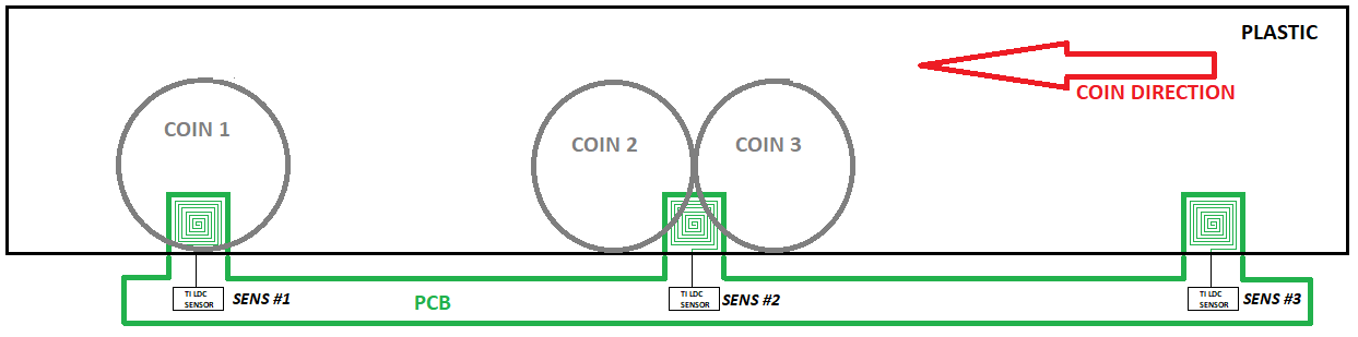
I am evaluating a TI inductive sensor as a soluction for detection of coin transit.
The operating principle is described in figure 1: the coin transit takes place on a flat plastic surface and the sensing elements (the spiral inductors) are underneath this plastic cover.
The main issue is that we cannot guarantee any free gap between two consecutive coins, nonetheless we must be able to distinguish the two coins.
Another important issue is that in our application the target (the coins) do not approach the inductor in front of it, but they approach sliding laterally.
We first started making some tests on the LDC1101EVM, but now we are focusing on the the LDC0851 because of its much simpler interface and I'll show you three different configurations with the LDC0851EVM.
1. Event counting
As you can see from the attached video (Mode1), the system manages to distinguish the two consecutive coins:
- the led blinks on with the first coin
- blinks off between the two coins
- then blinks on again with the second coin
The LDC0851 datasheet states (page 21) that "Two identical coils can be placed such that when one of the coils is covered by a gear tooth, the other is uncovered".
Unfortunately this is not our condition because for some moments two consecutive coins can cover, each one, both the spirals.
For this reason, I'm afraid that this working mode is not acceptable.
Moreover, to get the system working in this configurations, I must set the ADJ close to the maximum sensitivity, and I think that this is not a good starting point.
2. Event counting with stacked coils
The event counting with stacked coils is not considered in datasheet; anyway it seems that the system manages to distinguish the two consecutive coins, as well.
As you can see from the video (Mode2), I am trying to simulate a stacked coil by stacking two identical coil pcb; obviously this method should be validated by testing a more realistic couple of stacked coils on single pcb.
Here the ADJ is set to a medium sensitivity.
Is this working mode acceptable?
3. Threshold Adjust Mode for Distance Sensing Using Side by Side Coils
This configuration is similar with the one of page 13 of the datasheet with onlu one fundamental difference: the target approaches not frontally but laterally.
As you can see from the video (Mode3), the system works; but is acceptable that the target moves laterally towards the target?
I think that the best for us would be to adopt configuration 2 or 3, but I would like you if you can provide me with some considerations on this application and how appropriate and reliable are these working mode.
In other words, I have to be sure that my system is working properly.
It is understood that our main challenging task will be to design the spiral inductor optimizing it for the application.
Any help will be really appreciated.
Thank you in advance and best regards,