This thread has been locked.

If you have a related question, please click the "Ask a related question" button in the top right corner. The newly created question will be automatically linked to this question.

DRV5032: About Min/Max of sensor sensitivity

Part Number: DRV5032

Hi,

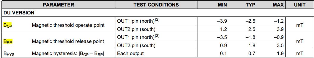
Customers want to specify Min/Max of sensor sensitivity in customer application.
Could you please tell me how to verify Min/Max recommended by TI with an actual device?
Customers are considering TI Hall sensors for the first time.
Therefore, Customer would like to know the procedure for verification and the evaluation method.
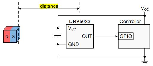
And When incorporating DRV5032 into an application, customer wants to specify Min/Max specifications for sensitivity that cover DRV5032 variations.

Best Regards
Yusuke

  • Hi Tsukui,

    To better understand the magnetic specifications of our hall sensors you can share the following  training series:

    In section 2 we cover ker specifications for all our sensor types including these switches. For the DRV5032 the magnetic specifications can be found in section 7.6 of the datasheet. Here you will see the Bop,Brp and hysteresis for all versions of the DRV5032.

  • Forgo to add. you can also look at the available EVMs for evaluation in this IC  product folder.

    www.ti.com/.../DRV5032

  • Hello Julio,

    Thank you for your kind support.
    I checked the video material "section2" and EVM information.
    I will distribute this information to our customers.

    I have additional questions about the actual application design.
    I fully understand that the specifications guaranteed as the DRV5032 are as follows.


    However, in actual applications, it is necessary to specify Min/Max for the detection sensitivity between the DRV5032 and the magnet.
    Especially how to evaluate the distance,Should customer determine the detection accuracy?
    Could you give me a general accuracy setting method or a customer design method example?


    Best Regards
    Yusuke

  • Yusuke-san,

    DRV5032 has a calculator tool which is available on the device landing page that will help calculate the distance for case where the pole is aligned with and moving directly toward the top of the package (orthogonal to the sensor) as you have drawn. It allows for various materials and geometries, and will suggest expected values for the maximum BOP and minimum BRP.

    The customer can use this to help find expected worst case values.  It is best practice to design around the extremes to ensure that all possible sensor thresholds will be able to detect the magnet position.  This may produce a variation in the actual trip point.  The goal will be to have start and stop points set to always cross these thresholds.

    Other online calculator tools exist as well that may be useful, such as

    https://www.kjmagnetics.com/fieldcalculator.asp

    Additionally they can create simulations of their setup using FEMM (Finite Element Method Magnetics) if they need to create more complex setups.

    http://www.femm.info/wiki/HomePage

    Starting from a calculated field is a very powerful starting point.  After that I would generally expect most customers will verify the design by gathering empirical lab data to verify desired functionality and tolerance.