This thread has been locked.

If you have a related question, please click the "Ask a related question" button in the top right corner. The newly created question will be automatically linked to this question.

LMT86: LMT86LPGM

Part Number: LMT86

Hello,

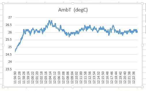
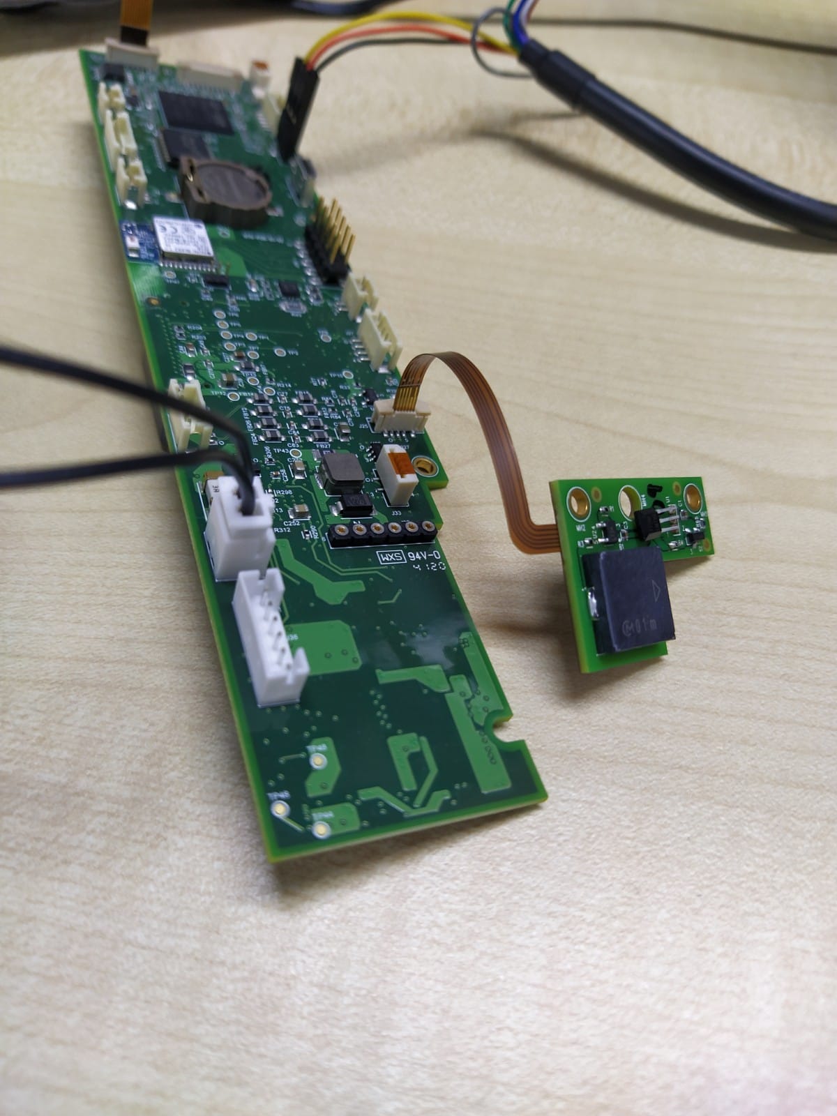
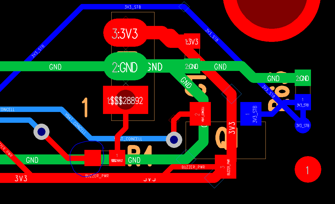
I am using LMT86LPGM for monitoring the ambient air temperature. I am facing a weird problem i.e when I turn on my PCB, I could see the temperature measured is quiet correct(about 27 degrees). But after some time the value shoots to very high like 150 degrees. This is happening with multiple sensors. I also checked the voltage on the output of the sensor and it shows 1.8V at the beginning of the test and suddenly starts to decrease to a very low value like 500mV. I am not able to find the root cause. Below is the temperature profile from one of the tests. Also attached is the schematics. I tried different values of series resistance on the sensor output line like 2.2K, 3K, 4.7K, but the problem persists.

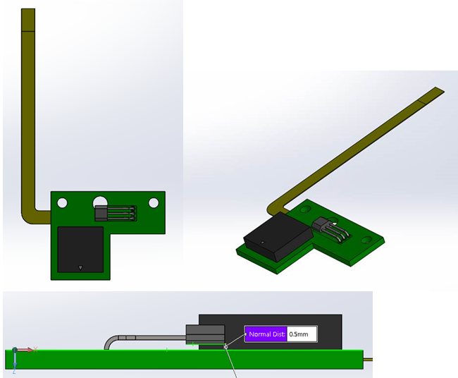
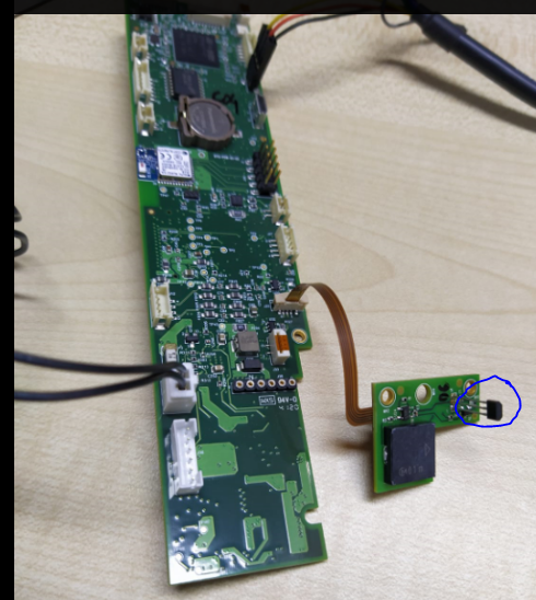
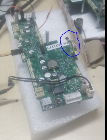
My sensor is mounted on a different PCB and that is connected to my MCU using Flex. Also, for proper mounting I have cut short the leads by 7mm . Can that cause this problem?

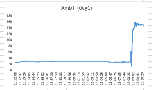
Kindly help with the possible root cause analysis and fixation to the problem.

Thanks,

Siddharth

  • Siddharth - 

    Thanks for posting!

    the image came through on the post, but the attachment with your schematic did not. Would you please try again to attach it? 

  • Hi Josh,

    Please find the attached screenshot of the schematic. 

    Thanks,

    Siddharth

  • Dear Siddharth - 

    the schematic seems incomplete - this looks to be two passives and a connector (which does not match the pinouts of the LP, LPG or LPM packages)

    If you can provide a layout and even images of your setup, that may also help us out here. 

  • Hi Josh,

    The schematic is correct. I have re-exported the schematic for you with the part name. It is not connector but the actual part. The pin out is also correct as per the LPG TO-92S package i.e Pin#1 is Output, Pin#2 is

    GND and Pin#3 is Vdd.

    The setup picture is shown below:

    The temperature sensor is marked with blue circle. The Sensor black part is not touching the PCB and is at a 5mm gap. The bigger board is the MCU board to which the sensor board is connected using flex PCB connection. Below is the 3D image of the temperature sensor board. The big black color square thing is a buzzer.

    I am writing below some of my observation which may help you to diagnose the situation.

    1. I checked a new board today I see the same behavior i.e it works for some minutes and then go bad, Below is the test graph. First 8 minutes its fine and it shoots to 160+ degrees.

    2. Initially, my thinking was this phenomena could be happening because of  the leads cut to short. But today I check again with a sensor with normal leads. I still see this happening with this setup. Below is the image of the board:

    Below is the test graph:

    2. In some cases , I saw after this abrupt behavior has happened, the resistance between the output pin and ground is 70-120 ohms. Generally before the start of the test, this is in mega ohms.

    But this is not true with all the boards. Some boards still shows the resistance ~230Kohms. But my feeling is if the board is on for a long time, eventually it may also end up around 70-120 ohms. So may be you can think how the sensor is working fine at the beginning of the test and eventually goes bad.

    3. I also checked with my older prototype board where  I used to connect the sensor to the MCU board using wired connector. Below is the image. Here the sensor leads are extremely short. Surprisingly, here I do not see this problem. There are some minor fluctuation, but not like the above 2 scenarios. the design is also same in terms of schematics.

    Setup image:

    Let me know if you need any further information.

    Thanks,

    Siddharth

  • Josh,

    The first image has some problem in uploading. I am re-uploading it here.

    Thanks,

    Siddharth

  • Siddharth - 

    thanks for the updates - I really don't see the issue yet - do you have the full schematic of that little board? Have you checked the voltage rail at the same time while you are testing the parts and did you confirm you have no bridges, etc. on the bareboard you are using? also, pls. think about any other changes you may have made in between board builds. the change in resistance of the device you noticed may be a clue that something external on that board or elsewhere in your system is the root cause.

  • Hi Josh,

    Attached is the full schematics. But other section are not relevant to the sensor. The only change between the revisions is that the current one has a PCB for the the sensor to mount which is connected to the MCU board using flex pcb which may add some additional capacitance. The old revision has the sensor mounted with wire and connecter on the mcu board. also, in the older rev, the sensor was very close to MCU. in the current one, it is slightly far. Other than that no changes.

    Thanks,

    SiddharthAWAK_Ambient_Temp_Sensor_Board_V2.0.pdf

  • Siddharth - 

    Thanks for the drawing! I have assigned this to Jalen, who will help you out from here. 

  • Hi Josh,

    I have an update for you. I have tested various scenarios today and found that if the sensor is mounted on the board as per the footprint in the datasheet, there seems to be some coupling between the GND  and the output pin of the sensor. The output starts to change in few minutes and it shows a lesser resistance between these 2 pins. If I terminate the test quickly, the sensor is still ok. But there is no physical short between the pins. May be if I leave it for long in that state, then eventually the resistance changes to lesser value.

    If I connected the output pin far from the ground pin, the system works. I tested for an hour or so. No issues observed.

    I am not sure why this is so. May be you van think and let me know.

    Thanks,

    Siddharth

  • Hi Siddharth,

    Are you referring to the layout in Figure 1? 

    If I understand correctly, you adjusted this layout and don't see the problem anymore? Can you share more details on the layout?

    Thanks,

    Jalen

    If I understand correctly, you are seeing coupling between the GND and Output?

  • Hi Jalen,

    I soldered the output pin to the other end of R4 resistor shown in blue circle in the below layout. And with this, I dont see the issue happening anymore.

  • Hi,

    Attaching the image once again.

    Thanks,

    Siddharth