This thread has been locked.

If you have a related question, please click the "Ask a related question" button in the top right corner. The newly created question will be automatically linked to this question.

AWR1843BOOST: AWR1843EVM Field of View settings in the Azimuth / Elevation Plane and Chirp Design

Part Number: AWR1843BOOST
Other Parts Discussed in Thread: TIDEP-01011, DCA1000EVM, AWR1843

Hello,

I am a beginner on the TI mmWave radar. I learned a lot from the examples from the automotive and industrial toolboxes. Thanks in advance. 

Currently, I am using the AWR1843EVM, I have some questions regarding to the FoV settings in the Azimuth and Elevation planes in the "mmWave Medium Range Radar Lab" and  "mmWave Parking Lab".

I have learnt the basic chirp settings in "mmr_config_chirp_design_USRRxx.h" and played the parameters in the mmwave sensing estimator. I have five questions listed as below. 

(1) Based on the requirements, max range, max velocity, range resolution, etc, both labs have defined particular chirp parameters used in "mmr_config_chirp_design_USRRxx.h". However, in the tutorial it also claimed the field of view in Azimuth and Elevation plane. For example, FoV of Azimuth from -50 degree to +50 degree, FoV of Elevation from -15 degree to +15 degree (reference: TIDEP-01011). In the demo code, mmr_18xx_dss and mmr_18xx_mss, where can I define those FoV for the Azimuth and Elevation plane? I am using mmWave SDK 3.5 and mmWave automotive toolbox 3.2.0

(2) In the "mmWave Medium Range Radar Lab", if I want to use only one mode, say the USRR subframe only. I should use "SUBFRAME_CONF_USRR" instead of SUBFRAME_CONF_MRR_USRR. However, I still need to include either mrr_config_chirp_design_MRR120.h or mrr_config_chirp_design_MRR80.h, otherwise it will give me compiling errors. Since I just want to want the single mode, say mrr_config_chirp_design_USRR50.h, will either mrr_config_chirp_design_MRR120.h or mrr_config_chirp_design_MRR80.h influence the USRR mode by including them?

(3) Thanks for giving more example in the chirp design. If I want to use the mrr_config_chirp_design_USRR50.h, how can I retrieve the design requirements, like the max range, max, velocity, range resolution, velocity resolution based the parameters defined in mrr_config_chirp_design_USRR50.h? Any reference for this header file?

(4) If I want to get data before the Clustering and Tracking algorithms run on the AWR1843, how should I modify the code to do it? Because I want to send those data to a local PC and run the clustering and tracking algorithm there. I also have a DCA1000EVM, should I use the UART or DCA1000EVM? 

(5) If I want to plot the doppler-range FFT heat map and azimuth-range FFT heat map of the mmWave Medium Range Radar Lab. How should I do it?

I know I ask a lot. Thanks a lot!!!

Best,

Hang

  • Hi,

    (1) Based on the requirements, max range, max velocity, range resolution, etc, both labs have defined particular chirp parameters used in "mmr_config_chirp_design_USRRxx.h". However, in the tutorial it also claimed the field of view in Azimuth and Elevation plane. For example, FoV of Azimuth from -50 degree to +50 degree, FoV of Elevation from -15 degree to +15 degree (reference: TIDEP-01011). In the demo code, mmr_18xx_dss and mmr_18xx_mss, where can I define those FoV for the Azimuth and Elevation plane? I am using mmWave SDK 3.5 and mmWave automotive toolbox 3.2.0.

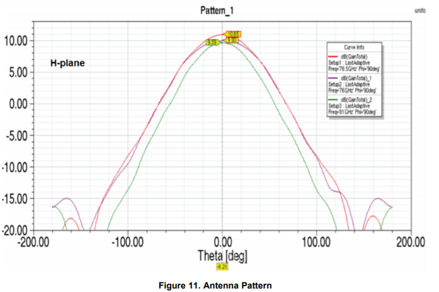
    [Answer] The FOV is a characteristic of the antenna. It is not configured in sw. Please see the EVM UG to see the Antenna Radiation Pattern

    (2) In the "mmWave Medium Range Radar Lab", if I want to use only one mode, say the USRR subframe only. I should use "SUBFRAME_CONF_USRR" instead of SUBFRAME_CONF_MRR_USRR. However, I still need to include either mrr_config_chirp_design_MRR120.h or mrr_config_chirp_design_MRR80.h, otherwise it will give me compiling errors. Since I just want to want the single mode, say mrr_config_chirp_design_USRR50.h, will either mrr_config_chirp_design_MRR120.h or mrr_config_chirp_design_MRR80.h influence the USRR mode by including them?

    [Answer] No this will not influence it

    (3) Thanks for giving more example in the chirp design. If I want to use the mrr_config_chirp_design_USRR50.h, how can I retrieve the design requirements, like the max range, max, velocity, range resolution, velocity resolution based the parameters defined in mrr_config_chirp_design_USRR50.h? Any reference for this header file?

    [Answer]

    You will be able to find the formula that defines the max range, ... in the training "Introduction to mmWave Sensing"

    (4) If I want to get data before the Clustering and Tracking algorithms run on the AWR1843, how should I modify the code to do it? Because I want to send those data to a local PC and run the clustering and tracking algorithm there. I also have a DCA1000EVM, should I use the UART or DCA1000EVM

    [Answer]

    With the DCA1000EVM you will be able to capture raw data and post process it in python or matlab.

    With the UART you will be able to get the data at run time.

    You would have to decide what is the best for you based on your project.

    (5) If I want to plot the doppler-range FFT heat map and azimuth-range FFT heat map of the mmWave Medium Range Radar Lab. How should I do it?

    [Answer] the range doppler heatmap is not saved internally. So this will require significant changes.

    Did you look at the mmWave SDK demo? It is also MIMO based and may have more features interesting to you

    thank you

    Cesar

  • Hi Cesar,

    Thank you very much for the reply. 

    For (1), I understand that the max FoV is from -90 to +90, because d = lamda/2. In the labs, for example, the parking lab, it claimed the FoV is from -50 to +50 (TIDEP-01011). Do you mean it shows the detection from -50 to +50, but the radar scans from -90 to +90? I know the equation for angle resolution in the azimuth plane, basically it depends on the number of rx antennas and d. Could you let me know how can I calculate the angle resolution in the elevation plane?

    For (2), solved. 

    For (3), I have gone through all the tutorials. Yes, I can try to figure it out by plugging the parameters. 

    For (4), if I want to use the uart to get the data before the clustering & tracking algorithm runs, in other words, disable the clustering and tracking algorithm, and send out the data through uart to PC. Could you give me suggestions on how to do it. For example, how to disable the disable the clustering and tracking algorithm in the mrr lab and where to modify the code to send out the data to PC?

    For (5), I will take a look DCA1000EVM first. Yes, I played with the OOB mmwave demo. However, I find the maximum distance it can detect is around 30m. I want to use the AWR1843 for a USRR project around 50-60m detection. Is it possible to change the OOB demo to that range and some specific resolution?

    Thank you so much for your generous help!

    Best,

    Hang


  • Hi Hang,

    1. The advertised angle is limited because the transmit antenna does not illuminate the objects as well if they are at angles(source). Due to this, the reflected signal of an object outside +-50 degrees might not be strong enough to be detected. As Cesar mentioned, this has to do with antenna design rather than the theoretical limit imposed by the angle estimation technique (which is indeed +-90 degrees for our antenna geometry)

    For the 1843 EVM, there are 8 virtual azimuth antennas and 4 virtual elevation antennas. You can use these to calculate the respective resolution.

    4. Both MRR and the OOB demo export the detected pointcloud with every frame. You can have a look at the TLV format in the developer's guide for more details.

    5. For the out of box demo, you can select "Best Range" as the desirable configuration in the demo visualizer. This should allow you to have configurations upto 50 meters.

    Regards,

    Aayush

  • Hi Aayush,

    Thank you so much! 

    Best,

    Hang