This thread has been locked.

If you have a related question, please click the "Ask a related question" button in the top right corner. The newly created question will be automatically linked to this question.

TMP116: Problem while entering in SD mode...

Part Number: TMP116
Other Parts Discussed in Thread: HDC2080

Hi all,

We are using the TMP116 in a battery powered application and it works fine to give temperature.

After entering SD mode, it still consume approx 100uA when it's defined to be at under 1uA in the datasheet.

Does someone has ever seen this problem.

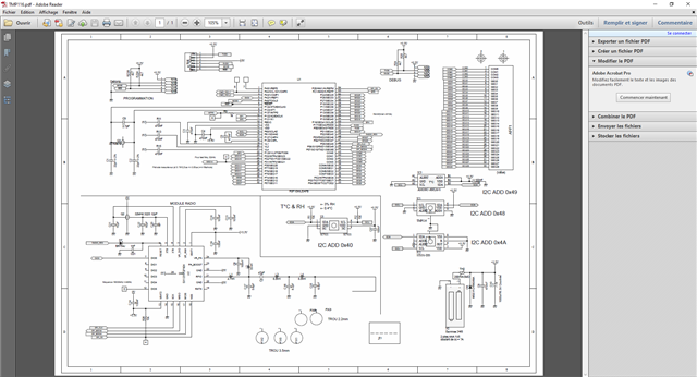
It has been on the same pcb as a SI7054 which consumes approx 1uA in SD mode so it doesn't seems to be a pcb design problem.

Is there something special to do in add to sending the powering down command?

Many thanks for help

Best regards

Phil

  • Hi Phil,

    Can you share your schematic?

    How are you measuring current?

    Is there other activity on your I2C bus while taking the measurement?

    thanks,

    ren

  • Hi Ren,

    Thank you for your answer.

    Please find attached our schematic.

    We do not send I2C frames, we put all the system in PD mode.

    We measure the current same way for testing all the T°C sensors.

    We have 4 different boards to test the sensors individually and isolate their own consumption.

    Bert regards

    Phil

  • Hi Phil,

    Have you written 01 to the MOD bits in the Configuration register? This is necessary to shutdown the TMP116. Some of these competitors you're testing don't take temperature measurements at power-on the way that TMP116 does. The TMP116 has to be told to shutdown. This makes it easier to retrieve temperature data from TMP116. If you write to the TMP116's EEPROM, you can change its default behavior at power-on. 

    I have to recommend that you provide TMP116 with it's own bypass capacitor, but this shouldn't cause the increased current that you're observing.

    Our HDC2080 and HDC202x products are direct replacements for the SI7021 device you're evaluating. Our device has better current consumption.

    thanks,

    ren

  • Hi Ren,

    I send you attached a copy of what we are writting to the TMP116.

    Seems that it's what you said in your answer but perhaps have we forgot something...

    If you can have a look.

    Thank you for the second source of the SI7021, it could be helpful !

    Best regards

    Phil

  • Phil - 

    Do you have a zoomed in image of that o'scope screen shot - the SCL line (in that image) looks like it is missing pulses and does not seem to match up with what the scope claims as decoded I2C protocol - it is hard to see, so if you have a better image, that would be great. 

  • Hi Josh,

    Thank you for your help, here find a new capture of our transmission.

    Best regards

  • Hi Phil,

    I can't see a reason for your current reading to be wrong unless there's something about your setup that you're not showing us. Is there anything else you can share? Have you observed this problem on more than one TMP116?

    thanks,

    ren

  • Phil - 

    thanks for the capture - please check what I decoded per bit for that sequence, and then check your firmware - here i think the decoder (in your scope) is thrown off by the extra clock cycle in the address byte. (because if you look at it from that extra clock, the next byte is a 0x01 with an ACK, the third byte would be 0x06 with ACK, etc.

  • Hi,

    OK...

    but I do not agree with the idea of extra clock
    I sent 9 clocks by bytes... =>   4* 9 = 36 clocks

    In my case, I2c is done by bitBanging ,
    this explain there are some larger clock ( due to interrupts)

    rem: I've done a test inhibitting interrupts but this dot change anything

    have you another Idea ?

    kind regards
    herve

  • Dear Herve - 

    on the first byte you sure do have 10 clock cycles, as I pointed out. I would also not suggest to bit-bang I2C, too much can go wrong, as we can see here. Does the Renesas controller have SDK you can leverage?

  • I do not agree
    for me , what you call extraclock, is the first clock of the next byte 

    are you agree that you can count  4*9 = 36 clocks  ?

    we do bit banging with this microcontroller for a lot of years and we have no problems....

    for me the TMP116 acknoledge the sent bytes...

    really do not see where is the pb !

    hope you can help a bit more

  • Dear Herve - 

    I don't consider the waveform you provided to be compliant with any I2C traffic I have ever seen, for any device, especially if you are considering that changing frequency mid traffic to be OK. 

    Here is an example of what the traffic should look like, here writing pointer to 0x01, on address 0x90. 

  • here is a capture of i2c dialog ( shutdown frame)
    without interrupt...but still bitbanging !

    reading temperature is OK
    trying one shot or periodic work fine ...
    so I think configuration of TMP116 work fine.

    I had problem, in shutdown mode  current is around  60uAmp on 2 prototypes boards
    still searching...

    kind regards
    herve

  • Herve - 

    Here is what it should look like

  • not exactly !

    after the ack, the bus is free =>  the sda line should go up with the pullup
    as you can see in my trace;-)

    So, do you see any problem in this trace ?


    in this design the thermal pad is connected to ground
    do you think it could explain the current consumption in standby mode ?

    kind regards
    herve

  • Perhaps after you send the STOP, you could release the SDA line on the MCU - and see if that is the source of the extra current draw.  

  • Hi Josh,

    i've just done the test releasing SDA after STOP
    and good new current go down  from 70uA to 35uA !!
    but need to go down to 10-15uA...

    any other idea ?

  • Dear Herve - 

    You are still an order of magnitude away from measuring the shutdown current of the TMP116. At room temperature, with I2C inactive, it should be 0.25uA to 0.5uA. Couple things to check that I can think of - 1. Ensure you are measuring only the TMP116, as you may have leakage current from the other sensors on the bus (back powering). 2. Double check your current measurement and the connections in general - use a four wire current measurement if possible - this current is so low, the leads of the meter might be getting in the way of the real measurement.   

  • Josh,

    you're right current is really low...

    I measure total current consumtion of my board when in sleep mode
    waiting a bit current goes down to 23uA
    with other  sensors Silabs/AMS/sensirion on same board I reach ~10uA

    do you think the fact , we connect thermal pad to ground could  
    and we let alert pin floating... could explain that ?


  • Dear Herve - 

    I think you might want to check the other devices are actually in shutdown - the current level you are seeing for all these parts is too high - the TMP116 is 0.5uA max for shutdown at room temp, the AS6200C is supposed to be 0.4uA max, Si7021 0.06uA with the STS3x-DIS being between 0.2uA and 6uA) , so measuring 10uA in this case means something is not in shutdown or you need to switch over to using 4 wire current measurement method. 

    To answer your last question, the TMP116 package thermal pad is not connected to the device ground and should be left unsoldered for the best measurement accuracy. If the thermal pad is soldered it must be left floating or connected to ground. The ALERT pin is open drain, since you are not using it, it can float. 

  • the TMP116 package thermal pad is not connecte

    I measure total current of my board with a low current amperemeter
    => mcu in sleep mode with lcd driver active + RF SX1231 in sleep mode

    with other  sensors I measure ~10uA

    still searching...

    thanks for your help

  • the R78 MCU will draw  5uA to 12uA when resonator is connected. Check your MCU is in STOP or HALT mode and all the (unused and used) pins are parked correctly so they are not drawing extra current. 

    https://www.digikey.jp/htmldatasheets/production/2911278/0/0/1/rl78-l13.html (note 8 on page 25, etc.)