This thread has been locked.

If you have a related question, please click the "Ask a related question" button in the top right corner. The newly created question will be automatically linked to this question.

MMWAVE-DFP: AWR1243boost + MMWAVE-DEVPACK combined. mmwavelink example fails with error -8. Blinking on mmwave-devpack DS11-DS14 and causes bluescreen.

Part Number: MMWAVE-DFP
Other Parts Discussed in Thread: AWR1243BOOST,

I have combined both the awr1243boost design and mmwave devpack board designs onto a single PCB. I attempted to keep all portions of the board the same, save for a few redundant traces in regards to communicating between the two boards. I have successfully programmed the XDS110 debug probe (TM4C chip), and the FTDI chip (I think), but when I plug into the FTDI USB port my computer will bluescreen with error "KERNEL SECURITY CHECK FAILURE". When I launch my computer into safe mode and connect the board I do not get blue screen. Additionally, while this happens the 4 LEDs on mmwave-devpack with labels DS11 to DS14 blink on and off.


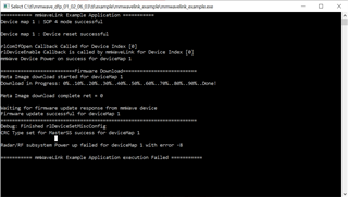
Unfortunately, when I am in safe mode, I am not able to use radarstudio. For some reason, the "RS232 Operations" section shows no options for COM ports and I suspect this is to do with being in safe mode. When I try to run mmwave link example from mmwave-dfp, the application fails at Radar/RF subsystem powerup. Any insight into what could be causing this failure would be appreciated. 

  • Hi,

    Looks like this FTDI usb cable is generating some of back current to PC (just crude guess) which is causing this PC reset. Make sure that all the connection on your custom board is as per AWR1243BOOST/DevPack schematic.

    DFP example uses FTDI COM connection to communicate over SPI to the AWR device. so it won't work if FTDI connection is not available.

    Regards,

    Jitendra

  • Hello Zion,

    What are the DS11 and DS14 LEDs connected to on your board? Can you share the schematics of your board?

    Regards,
    Vivek

  • Attached is a PDF of our schematic. We tried to keep the design very very similar to AWR1243boost + mmWave-Devpack. 

    I do have one question about the schematic from TI. In the below picture, how can R29 be DNI, while R26 is inserted? Wouldn't both of these have to be connected to enable UART communications? Regardless, this resistor is also DNI on our design (the schematic has an error for this resistor, but I have double checked the BOM and fabricated boards and this resistor is removed).

    DS11 is connected to FTDI_NRST net which goes to the FTDI GPIO bus (C6 port), and also to AR_NRST_MCU through the U20 IC switch. 
    DS14 is connected to FTDI_SYNC_OUT_SOR2 net which goes to the FTDI GPIO bus (D3 port), and also to MCU_SOP0 through U20 IC switch.

    AWR1243.pdf

  • Hello Zion,

    The FTDI_UART4_TX port is a single pin UART logger pin (BSS_Logger). Hence R26 is mounted. the RS232 pins are not connected to the FTDI chipset by default , they are connected to the TM4C chipset. Hence R29 and R27 are DNI.

    I could be that the USB port you are connecting to is unable to provide the power needed for the FTDI chipset. Can you connect the USB cable to a 5V wall mount  charger instead and observe if the LEDs are stable?

    Regards,Vivek