This thread has been locked.

If you have a related question, please click the "Ask a related question" button in the top right corner. The newly created question will be automatically linked to this question.

TDC1000-C2000EVM: TDC1000-C2000EVM ' problem

Part Number: TDC1000-C2000EVM
Other Parts Discussed in Thread: TDC1000, MSP430FR6047

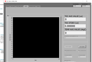
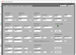
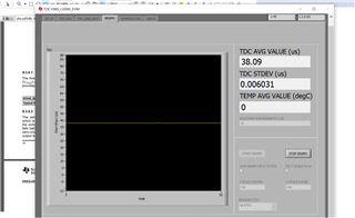
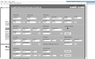
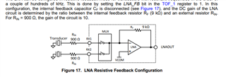
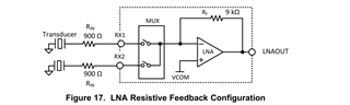
TDC1000-C2000EVM don't work if i choose the LNA_FB in capacitive state ,however,if Ichoose the resistance state ,the TDC1000-C2000 EVM GUI graph will work even without a transducer(the transducer don't connect to the board)

  • Hello Lei,

    When you tried the LNA_FB in capacitive state did you populate a capacitor for in place for RIN1 and RIN2 and try it with a transducer? Or was it tested without the transducer like you mentioned for the resistive state? 

    I tried it in the capacitive state without populating a capacitor and did not get any readings, when I tried the resistive state it would only work if the gain was high enough (like in your image with a max gain of 21dB) or if I touched the input pin directly. I believe it was picking up some sort of noise and that was getting amplified greatly hence why you are seeing the GUI graph behave like it received an input.

    Best,

    Isaac

  • Thank you.

    First of all, I connected the sensor in the capacitive state, but it is a sensor set by myself. The resonant frequency is 300K HZ, but there is no external capacitor or resistor. I want to know how to connect the external capacitor or resistor, and I want to know how to use my own 300K hz ultrasonic transducer for flow measurement (mainly refers to how to connect capacitors and resistors, which specific pins are connected to the EVM is not clear), I look forward to your reply

  • Hello Lei,

    The capacitors and resistors for the input are all external to the board connecting from the transducers negative pin to either input RX1 or RX2 of the TDC1000 EVM board. This is only meant to affect the input by either amplifying or providing extra filtering hence why they are not connected to the TX1 or TX2 side of the pins. The resistors and capacitors are referred to as Rin and Cin in the data sheet you may read about this in section 8.3.3.

    If you are going to use a 300kHz transducer and you are using the internal clock (8MHz) then you have to ensure that you are changing the value to divide by 32 in order to get close to the target frequency of 300kHz. If you are using an external clock then make sure the clock is divided appropriately to achieve a frequency close to your transducers resonant frequency. You can read about this in section 8.3.1 of the data sheet.

    One last thing to note is that the TDC1000 has an issue with accuracy during flow metering since it cannot appropriately detect zero flow. Here is a thread that you can read: https://e2e.ti.com/support/sensors/f/sensors-forum/946044/tdc1000-water-flow-metering/3508151?tisearch=e2e-sitesearch&keymatch=TDC1000-C2000%20flow%20metering%20FAQ#3508151

    We typically suggest using an MSP430FR6047 for such measurements. Here is a TI reference design that you can look into: www.ti.com/.../TIDM-02005

    Best,

    Isaac

  • I want to know if there is a way to increase the amplification factor of the LNA, instead of just relying on the 10 times gain of its own amplification

  • Hey Lei,

    As mentioned in the datasheet the gain is dependent on the outboard resistor Rin, Rf/Rin = Gain provided by the LNA. In the examples given they are using a 900 ohm resistor for Rin. So 9000/900 = 10. I have attached a screenshot of where it is mentioned in the data sheet. If you change the value for Rin it may be possible to get additional amplification, but the datasheet does indicate that it is designed to be a 20dB inverting amplifier so going beyond this might introduce unwanted elements to the signal. One thing to note since there is a capacitor in the feedback loop in parallel with Rf (9k resistor) you are also creating a low pass filter so if you plan on changing the value of Rin I would ensure you are not accidentally attenuating your signal.

    But if more gain is needed you can use the gain in the PGA that provides up to an additional 21dB of gain. I would also recommend probing your return signal path to check the amplitude of the return echoes. This should help you determine how much gain you actually need from your system.

    Best,

    Isaac

  • Thank you, I need to confirm that when using the LNA with resistance feedback mode, I need to configure on this circuit, do I directly replace the C5and C4 capacitors on the circuit board with my own resistance, or talk about some more specific methods , Because I am measuring the flow rate when the flow rate is 0, and the ΔTOF data obtained is about 40 microseconds. This indicates that there is a big problem in our ultrasonic reception. I suspect that the LNA magnification is not enough. I want to know the specific configuration method of the LNA. , The more specific the better. Hope you can reply me as soon as possible thanks


  • Hello Lei,

    In order to increase the gain of the LNA when using resistive feedback mode a resistor needs to be placed from the transducer to the appropriate J5 connector of the channel you are using. There are no onboard resistors for this setup the resistors would be external going from transducer to the boards input. Capacitors C4 and C5 are part of an external low pass filter between the PGAOUT stages and  COMPIN so those are not to be replaced with resistors.

    I will respond to your 0 flow rate question in the other post you have made thank you.

    Best,

    Isaac