This thread has been locked.

If you have a related question, please click the "Ask a related question" button in the top right corner. The newly created question will be automatically linked to this question.

tdc1000-c2000evm measurements steel 2 and 4mm thickness

Other Parts Discussed in Thread: TDC1000-C2000EVM, TIDA-00322, TDC1000, TDC7200

Hello,
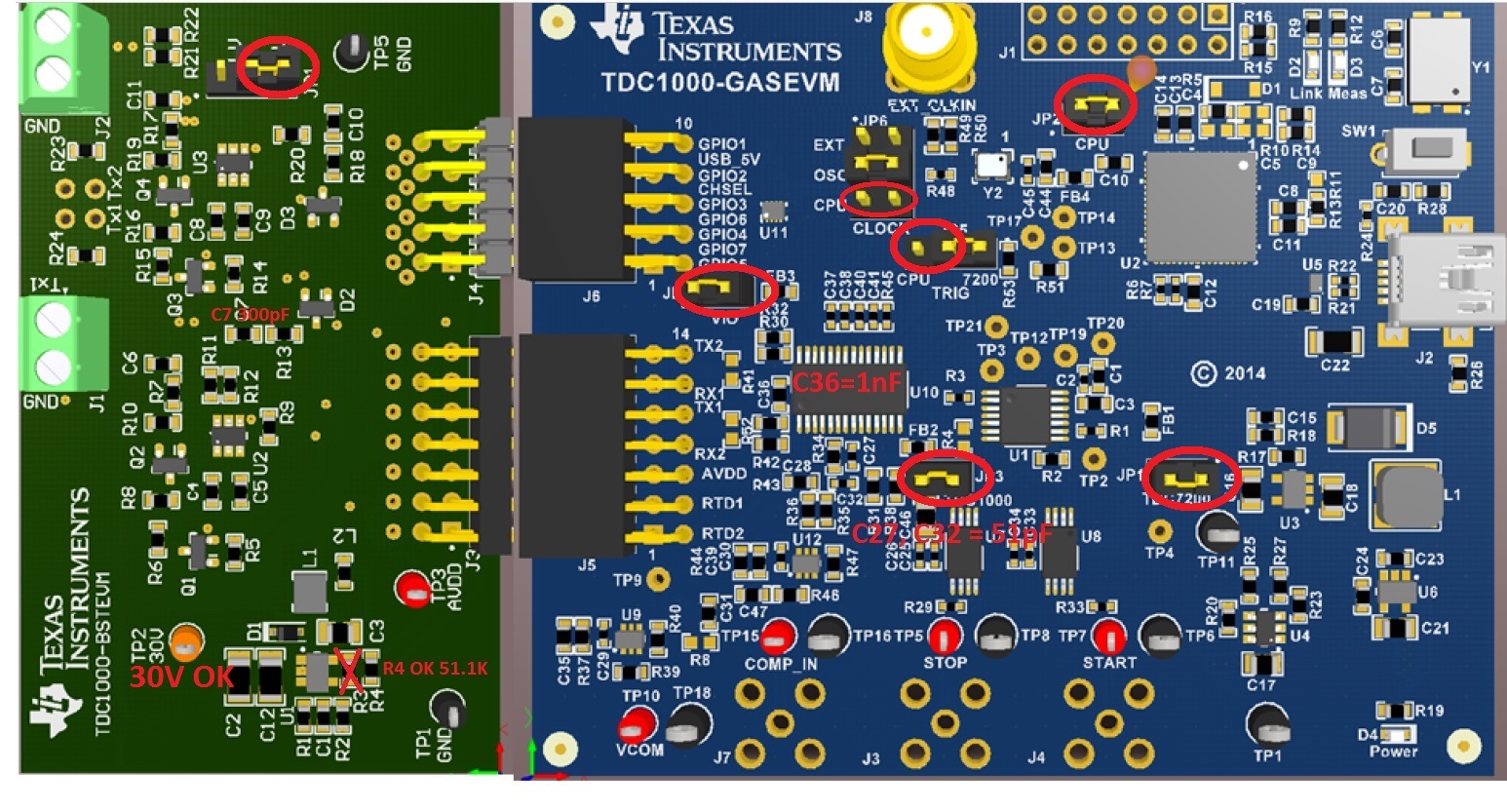
I am using the ultrasonic transducer SMD15T21R111WL with the development kit www.ti.com/.../tdc1000-c2000evm
I tried it in small containers of acrylic and metal and it worked
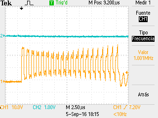
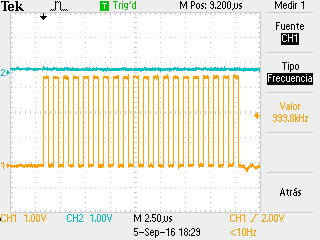
But it has not worked in large containers, my tank is a steel cylinder with a thickness of 2 and 4 mm, the cacateristicas cylinder are 85cm in diameter, 150cm long, the sensor is placed on the curved surface and the idea is to measure the level liquid (diesel), I followed the steps for installation (www.ti.com/.../snaa266a.pdf) but do not get measurement when I filled the tank, I can do to take the Transducer correct measurement, my Transducer is correct? or recommendation I can give for this type of measurement?

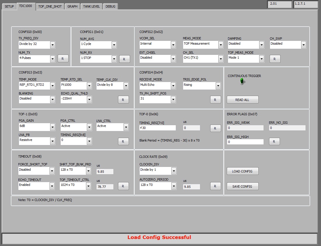
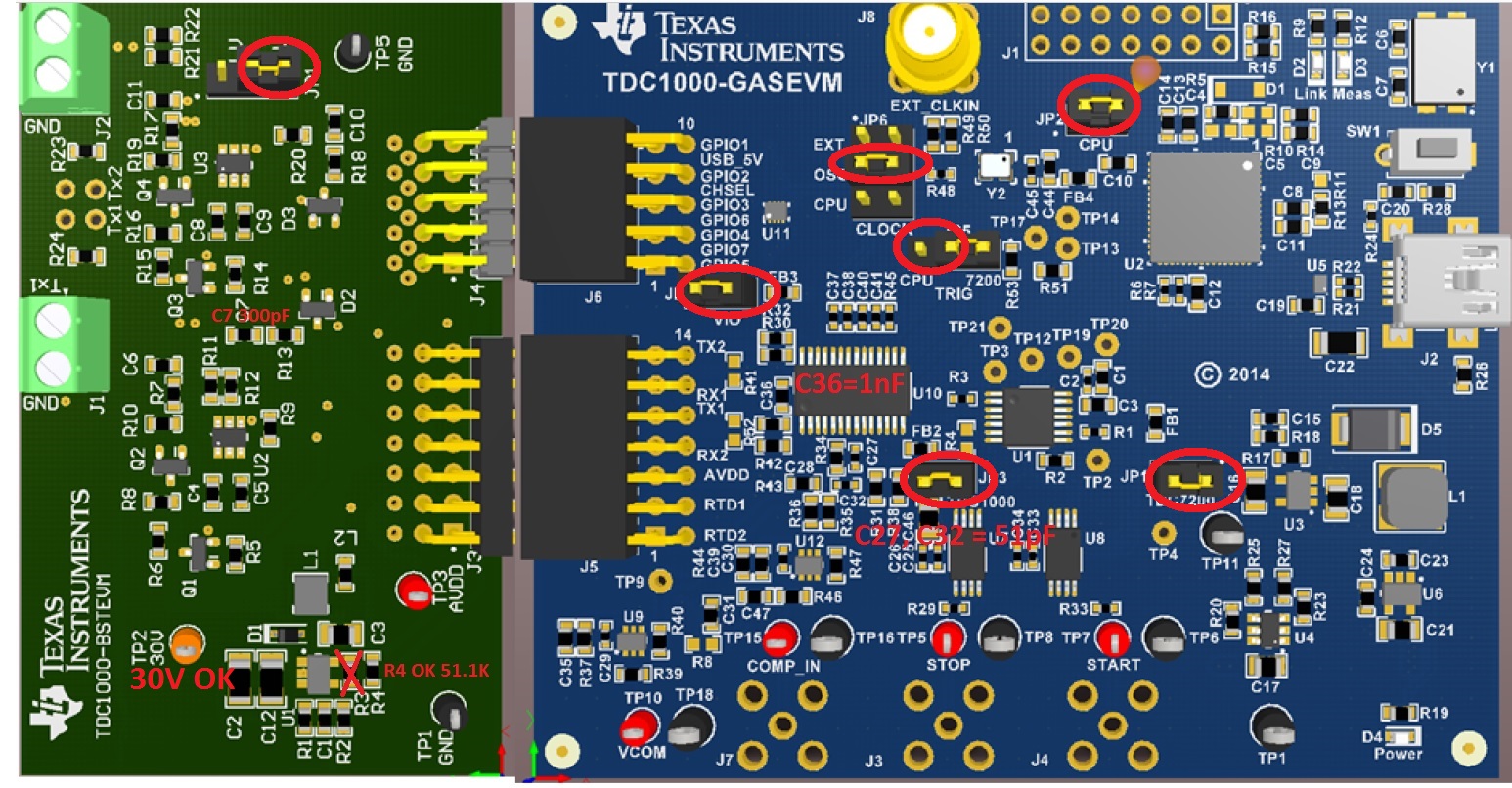
Based on the application note (www.ti.com/.../sniu026a.pdf) increase the voltage to 18VDC in the exitacion transducer (I have the UCC27531DBVR component, so not I could increase the voltage to 30VDC) is performed by components that had on hand, even though I failed to make a correct measurement in my Transducer mounted on the tank.
Does anyone has been able to perform measurements in conditions similar to mine with evm tdc1000-c2000evm ?..
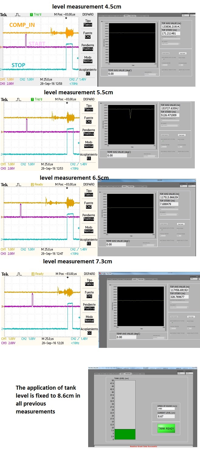
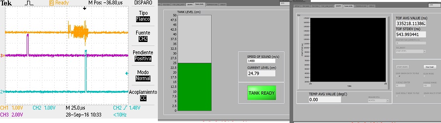
I tested with different parameters in the application NUM-TX (4,10,20,30 pulses) and ECHO_QUAL_THLD (-35, -50, -125, -220, -410, -1500mV) and still not get good results .
What is the recommendation TI?

Regards

Uriel

  • Uriel,

    Applying higher excitation voltage is the correct way. To measure 150cm level through 4mm steel, you need probably higher excitation voltage than 18V. Did you lower the level to say 10cm and check if you get any echo on the COMP_IN terminal?

    You mention sensor is placed on the curved surface. Make sure there's good uniform coupling between the transducer and the steel surface without air gap. I understand sometimes a cylinder of gel (need to be a good couplant of ultransonic energy) is used in-between so there is no loss. Otherwise air gap can greatly attenuate the ultrasonic energy.

    Please check TIDA-00322 schematic
    www.ti.com/.../tidrbi0

    It has an example high voltage boost circuit (that can go up to 30V) if you want to prototype with.

    Also, we have TDC1000GASEVM (not C2000 based) with boost circuit that can go up to 30V.

    Thanks,
    Vishy
  • Vishy,
    Now I have the EVM TDC1000-GASEVM and I use to measure liquid level (water / diesel) in a tank, the changes I made were as follows
    this link

    and I have the following Disc Transducer

    www.steminc.com/.../piezo-ceramic-disc-10x2mm-r-215-khz
    www.steminc.com/.../piezo-ceramic-disc-1-mhz
    www.steminc.com/.../piezo-ceramic-disc-20x21mm-r-10-mhz
    www.steminc.com/.../piezo-ceramic-disc-25x21mm-r-1-mhz
    www.steminc.com/.../piezo-ceramic-disc-30x21mm-r-1-mhz
    www.steminc.com/.../piezo-electric-disc-50x21mm-r-1-mhz

    I tested and I have not had good results.
    I've tried different files generated by these links and have not received data from the transducers
    webench.ti.com/.../index.html
    https://webench.ti.com/webench5/TDC/index.html?app=levelHead

    Previously use the EVM tdc1000-c2000evm could measure water level in small containers (20cmm) and it worked.
    following its recommendation acquired the TDC1000GASEVM but I have not been able to obtain valid data, attached one configuration I tested, though I've already changed NUM_TX, NUM_RX, ECHO_QUAL_TLH, etc.

    Regards

  • Uriel,
    Please share what's the jumper settings on your TDC1000-GASEVM. The board by default is set up CPU clock. Are you seeing the 30V TX excitation pulses properly? Do you see a echo on the COMP_IN terminal?

    Take a look at this posting

    e2e.ti.com/.../483410

    I explain in the above posting how to make sure at first you are seeing the TX excitation pulses at 30V properly. Let me know if you follow it and have questions. If needed, I can post an updated CONFIG file for your 1MHz transducer.

    Thanks,
    Vishy
  • Vishy,

    This configuration have in the EVM

    This is the application configuration

    the sensor used is the below.

    www.steminc.com/.../ultrasonic-gas-flow-sensor-200-khz

    This is what I get on the oscilloscope

    So far not been successful.

    Regards

  • Uriel,

    Since this GASEVM board has been setup for 1MHz transducer, please use the enclosed configuration file

    TDC1000_Config0                         14
    TDC1000_Config1                         41
    TDC1000_Config2                         00
    TDC1000_Config3                         04
    TDC1000_Config4                         5F
    TDC1000_TOF-1                           03
    TDC1000_TOF-0                           FF
    TDC1000_Error_Flags                     00
    TDC1000_Timeout                         23
    TDC1000_Clock_Rate                      00
    TDC1000_Conts_Trigger                   01
    TDC7200_Config1                         02
    TDC7200_Config2                         40
    TDC7200_Interrupt_Status                07
    TDC7200_Interrupt_Mask                  07
    TDC7200_Coarse_Cntr_Ov_H                FF
    TDC7200_Coarse_Cntr_Ov_L                FF
    TDC7200_Clock_Cntr_Ov_H                 FF
    TDC7200_Clock_Cntr_Ov_L                 FF
    TDC7200_Clock_Cntr_Stop_Mask_H          00
    TDC7200_Clock_Cntr_Stop_Mask_L          00
    TRIGGER_UPDATE_FREQ                     0004
    TDC_AVG/STDEV_NUM_ELEMS                 0032
    SAVE_GRAPH_DATA_TO_FILE                 00
    FLOW_MODE_SELECT                        00
    Y-SCALE_CENTER                          0000
    X-SCALE_RANGE                           0032
    MEASURE_RTD1                            00
    SAVE_RESULT_REGR_TO_FILE                00
    GRAPH_MULTI_STOPS                       00
    TDC_SELECT                              00
    TEMP_RTD_SELECT                         00
    TEMP_RTD_MODE                           01
    TEMP_AVG/STDEV_NUM_ELEMS                000A
    SAVE_TEMP_DATA                          00
    GRAPH_YMAX_DATA                         0000000000029810
    GRAPH_YMIN_DATA                         0000000000004E20
    TDC1000-HV_DRV_EN1                      01
    TDC1000-HV_DRV_EN2                      01
    HV_DRV_EN1_Period                       02BC
    HV_DRV_EN2_Period                       02BC
    ENABLE_POWER_CYCLE                      00
    CLK_FREQ_(1-16MHz)                      2.000000
    CLK_SOURCE_SEL                          03
    CPU_CLK_FREQ                            0C
    CPU_CLK_EN                              01
    TDC1000-HV_BST_PWR_EN                   01
    HV_BST_PWR_EN_Period                    0000
    FWD2REV_FLOW_DELAY                      0000
    TDC1000-IMPE_MATCH_EN                   00
    ENABLE_UART_STREAM                      00
    ENABLE_MSP430TIMER_TDC                  00

    A few things about this configuration file

    a) It assumes your GASEVM JP6 jumper is set as CPU clock, not onboard clock.

    b) Other jumper settings as you show above are fine

    c) I enclose above a config file. From the GUI, you can load this config file when you start to debug. It automatically sets up all the parameters and registers for  you. If you modify something, you can save and update the file as well. You do config file load and save operations by using "Load Config" and "Save Config" buttons of the TDC1000 (or TDC7200) tab of the GUI. 

    c) After loading the config file, first you probe TX1 pin (J1) of the TDC1000-BSTEVM, and should see 20 30V pulses (1MHz freq). Please confirm you see this. 

    d) You can also check GASEVM board J5.10. There you should see 20 3.6V pulses (1MHz freq).

    Once you get this going, then we debug the RX path. 

    Thanks, 

    Vishy

  • Vishy,

    Make the changes that indicated me, change the jumper JP6 to CPU Clock
    Load the configuration file that sent me,
    The signal was generated in TDC1000-BSTEVM J1 it is as follows:


    Also in J5 pin 10 I get the signal by 20 pulses of 1 MHz.

    What are the next steps?

    Regards.

  • Uriel,

    a) At J5.10, the TX output 20 pulses is clean but at J1 it looks very noisy and seems to be riding on something. Please debug this. May be some modification on the BSTEVM is causing this issue? Do you have transducer connected at TX1? How is it without the transducer. Try a board without any modification and see.

    b) For debugging RX path, please use the enclosed config below as a starting point. Keep water level fixed to say about 100us TOF. Use the equation TOF = 2 x D / C, where C is the speed of sound of sound in water (1480m/s), to find the corresponding level D. As explained in the app note SNAA270 observe if you are receiving a proper echo at 100us from the start pulse. You can observe START, STOP and echo pulses at TP5, TP6, and COMP_IN terminals and debug your setup. 

    TDC1000_Config0                         14
    TDC1000_Config1                         41
    TDC1000_Config2                         00
    TDC1000_Config3                         04
    TDC1000_Config4                         5F
    TDC1000_TOF-1                           80
    TDC1000_TOF-0                           1E
    TDC1000_Error_Flags                     00
    TDC1000_Timeout                         23
    TDC1000_Clock_Rate                      00
    TDC1000_Conts_Trigger                   01
    TDC7200_Config1                         02
    TDC7200_Config2                         40
    TDC7200_Interrupt_Status                07
    TDC7200_Interrupt_Mask                  07
    TDC7200_Coarse_Cntr_Ov_H                FF
    TDC7200_Coarse_Cntr_Ov_L                FF
    TDC7200_Clock_Cntr_Ov_H                 FF
    TDC7200_Clock_Cntr_Ov_L                 FF
    TDC7200_Clock_Cntr_Stop_Mask_H          00
    TDC7200_Clock_Cntr_Stop_Mask_L          00
    TRIGGER_UPDATE_FREQ                     0004
    TDC_AVG/STDEV_NUM_ELEMS                 0032
    SAVE_GRAPH_DATA_TO_FILE                 00
    FLOW_MODE_SELECT                        00
    Y-SCALE_CENTER                          0000
    X-SCALE_RANGE                           0032
    MEASURE_RTD1                            00
    SAVE_RESULT_REGR_TO_FILE                00
    GRAPH_MULTI_STOPS                       00
    TDC_SELECT                              00
    TEMP_RTD_SELECT                         00
    TEMP_RTD_MODE                           01
    TEMP_AVG/STDEV_NUM_ELEMS                000A
    SAVE_TEMP_DATA                          00
    GRAPH_YMAX_DATA                         0000000000029810
    GRAPH_YMIN_DATA                         0000000000004E20
    TDC1000-HV_DRV_EN1                      01
    TDC1000-HV_DRV_EN2                      01
    HV_DRV_EN1_Period                       02BC
    HV_DRV_EN2_Period                       02BC
    ENABLE_POWER_CYCLE                      00
    CLK_FREQ_(1-16MHz)                      2.000000
    CLK_SOURCE_SEL                          02
    CPU_CLK_FREQ                            0C
    CPU_CLK_EN                              01
    TDC1000-HV_BST_PWR_EN                   01
    HV_BST_PWR_EN_Period                    0000
    FWD2REV_FLOW_DELAY                      0000
    TDC1000-IMPE_MATCH_EN                   00
    ENABLE_UART_STREAM                      00
    ENABLE_MSP430TIMER_TDC                  00

    c) Pls review TDC1000 and TDC7200 data sheet for details of the register settings and their correct selection for level measurement.

    d) Also, I assume you have taken care to glue the transducer properly.  FYI, in app note SNA266, CYA is to ensure strong connection between the face of the transducer and the tank wall. Also, its low compressibility ensures there is no acoustic dampening. Whereas the glue, that is applied around the transducer circumference and backside, is for acoustic dampening (due to its flexibility) and wire strain relief. So the glue, if applied on the transducer frontside, can cause performance degradation and you may not see any echo.

    Thanks,

    Vishy

  • Hello Vishy,
    I have obtained a better response with the parameters configured as shown and the configuration file attached.

    TDC1000_Config0                         4A
    TDC1000_Config1                         41
    TDC1000_Config2                         00
    TDC1000_Config3                         02
    TDC1000_Config4                         5F
    TDC1000_TOF-1                           40
    TDC1000_TOF-0                           1E
    TDC1000_Error_Flags                     00
    TDC1000_Timeout                         23
    TDC1000_Clock_Rate                      01
    TDC1000_Conts_Trigger                   01
    TDC7200_Config1                         02
    TDC7200_Config2                         40
    TDC7200_Interrupt_Status                07
    TDC7200_Interrupt_Mask                  07
    TDC7200_Coarse_Cntr_Ov_H                FF
    TDC7200_Coarse_Cntr_Ov_L                FF
    TDC7200_Clock_Cntr_Ov_H                 FF
    TDC7200_Clock_Cntr_Ov_L                 FF
    TDC7200_Clock_Cntr_Stop_Mask_H          00
    TDC7200_Clock_Cntr_Stop_Mask_L          00
    TRIGGER_UPDATE_FREQ                     0001
    TDC_AVG/STDEV_NUM_ELEMS                 000A
    SAVE_GRAPH_DATA_TO_FILE                 00
    FLOW_MODE_SELECT                        00
    Y-SCALE_CENTER                          0032
    X-SCALE_RANGE                           0032
    MEASURE_RTD1                            00
    SAVE_RESULT_REGR_TO_FILE                00
    GRAPH_MULTI_STOPS                       00
    TDC_SELECT                              00
    TEMP_RTD_SELECT                         00
    TEMP_RTD_MODE                           01
    TEMP_AVG/STDEV_NUM_ELEMS                000A
    SAVE_TEMP_DATA                          00
    GRAPH_YMAX_DATA                         00000000005238B3
    GRAPH_YMIN_DATA                         000000000052384F
    TDC1000-HV_DRV_EN1                      01
    TDC1000-HV_DRV_EN2                      01
    HV_DRV_EN1_Period                       001E
    HV_DRV_EN2_Period                       001E
    ENABLE_POWER_CYCLE                      00
    CLK_FREQ_(1-16MHz)                     13.000000
    CLK_SOURCE_SEL                          01
    CPU_CLK_FREQ                            05
    CPU_CLK_EN                              00
    TDC1000-HV_BST_PWR_EN                   01
    HV_BST_PWR_EN_Period                    3A98
    FWD2REV_FLOW_DELAY                      0000
    TDC1000-IMPE_MATCH_EN                   01
    ENABLE_UART_STREAM                      00
    ENABLE_MSP430TIMER_TDC                  01

    The problem I have now is that I can not measure below 8.6cm, and more than 45cm.
    (The reading range is 8.6 to 45cm)
    I tested with two types of sensors the
    SMD15T21R111WL
    smd25t21f1000r
    and the two I get the same answer the increasing number of pulses at the maximum (31 pulses) I can not measure up to 47cm but more.

    Parameters that you recommend me to measure the full range?
    Or any way to get the correct settings.
    Note.
    When I get over 45cm AVG Value TOF and TOF STDEV remain fixed and not change if the water level increase, this also happens 8.6cm below.

    the sensors that are right for my application? (1.20mts metal tank with 2mm thick)?
    I have reviewed the application note
    www.ti.com/.../TIDA-00322
    and I see no problems for measurement,
    what parameters they charged for the NEXT test?

    Regards

  • I will review and get back to you. Thanks, Vishy
  • I reviewed your config file and upload here two updated files. For 1MHz transducer, you are using TX freq of 1.625Mhz (13MHz clock/8). This is not ideal. In updated file1 below, I didn't change this. So you can first try with that w/o changing any jumper settings on your board. For loading and running file 2, please change JP6 jumper position to CPU.

    TDC1000_Config0                         4A
    TDC1000_Config1                         41
    TDC1000_Config2                         00
    TDC1000_Config3                         02
    TDC1000_Config4                         5F
    TDC1000_TOF-1                           40
    TDC1000_TOF-0                           1E
    TDC1000_Error_Flags                     00
    TDC1000_Timeout                         23
    TDC1000_Clock_Rate                      04
    TDC1000_Conts_Trigger                   01
    TDC7200_Config1                         02
    TDC7200_Config2                         40
    TDC7200_Interrupt_Status                07
    TDC7200_Interrupt_Mask                  07
    TDC7200_Coarse_Cntr_Ov_H                FF
    TDC7200_Coarse_Cntr_Ov_L                FF
    TDC7200_Clock_Cntr_Ov_H                 FF
    TDC7200_Clock_Cntr_Ov_L                 FF
    TDC7200_Clock_Cntr_Stop_Mask_H          00
    TDC7200_Clock_Cntr_Stop_Mask_L          00
    TRIGGER_UPDATE_FREQ                     0001
    TDC_AVG/STDEV_NUM_ELEMS                 000A
    SAVE_GRAPH_DATA_TO_FILE                 00
    FLOW_MODE_SELECT                        00
    Y-SCALE_CENTER                          0032
    X-SCALE_RANGE                           0032
    MEASURE_RTD1                            00
    SAVE_RESULT_REGR_TO_FILE                00
    GRAPH_MULTI_STOPS                       00
    TDC_SELECT                              00
    TEMP_RTD_SELECT                         00
    TEMP_RTD_MODE                           01
    TEMP_AVG/STDEV_NUM_ELEMS                000A
    SAVE_TEMP_DATA                          00
    GRAPH_YMAX_DATA                         00000000005238B3
    GRAPH_YMIN_DATA                         000000000052384F
    TDC1000-HV_DRV_EN1                      01
    TDC1000-HV_DRV_EN2                      01
    HV_DRV_EN1_Period                       0064
    HV_DRV_EN2_Period                       0064
    ENABLE_POWER_CYCLE                      00
    CLK_FREQ_(1-16MHz)                     13.000000
    CLK_SOURCE_SEL                          01
    CPU_CLK_FREQ                            05
    CPU_CLK_EN                              00
    TDC1000-HV_BST_PWR_EN                   01
    HV_BST_PWR_EN_Period                    0000
    FWD2REV_FLOW_DELAY                      0000
    TDC1000-IMPE_MATCH_EN                   01
    ENABLE_UART_STREAM                      00
    ENABLE_MSP430TIMER_TDC                  01

    TDC1000_Config0                         0A
    TDC1000_Config1                         41
    TDC1000_Config2                         00
    TDC1000_Config3                         02
    TDC1000_Config4                         5F
    TDC1000_TOF-1                           40
    TDC1000_TOF-0                           1E
    TDC1000_Error_Flags                     00
    TDC1000_Timeout                         23
    TDC1000_Clock_Rate                      01
    TDC1000_Conts_Trigger                   01
    TDC7200_Config1                         02
    TDC7200_Config2                         40
    TDC7200_Interrupt_Status                07
    TDC7200_Interrupt_Mask                  07
    TDC7200_Coarse_Cntr_Ov_H                FF
    TDC7200_Coarse_Cntr_Ov_L                FF
    TDC7200_Clock_Cntr_Ov_H                 FF
    TDC7200_Clock_Cntr_Ov_L                 FF
    TDC7200_Clock_Cntr_Stop_Mask_H          00
    TDC7200_Clock_Cntr_Stop_Mask_L          00
    TRIGGER_UPDATE_FREQ                     0001
    TDC_AVG/STDEV_NUM_ELEMS                 000A
    SAVE_GRAPH_DATA_TO_FILE                 00
    FLOW_MODE_SELECT                        00
    Y-SCALE_CENTER                          0032
    X-SCALE_RANGE                           0032
    MEASURE_RTD1                            00
    SAVE_RESULT_REGR_TO_FILE                00
    GRAPH_MULTI_STOPS                       00
    TDC_SELECT                              00
    TEMP_RTD_SELECT                         00
    TEMP_RTD_MODE                           01
    TEMP_AVG/STDEV_NUM_ELEMS                000A
    SAVE_TEMP_DATA                          00
    GRAPH_YMAX_DATA                         00000000005238B3
    GRAPH_YMIN_DATA                         000000000052384F
    TDC1000-HV_DRV_EN1                      01
    TDC1000-HV_DRV_EN2                      01
    HV_DRV_EN1_Period                       01F4
    HV_DRV_EN2_Period                       01F4
    ENABLE_POWER_CYCLE                      00
    CLK_FREQ_(1-16MHz)                      2.000000
    CLK_SOURCE_SEL                          03
    CPU_CLK_FREQ                            0C
    CPU_CLK_EN                              01
    TDC1000-HV_BST_PWR_EN                   01
    HV_BST_PWR_EN_Period                    0000
    FWD2REV_FLOW_DELAY                      0000
    TDC1000-IMPE_MATCH_EN                   01
    ENABLE_UART_STREAM                      00
    ENABLE_MSP430TIMER_TDC                  01

    thanks,

    vishy

  • Hello,
    Sorry Vishy , I realized that the configuration file you send is not correct.

    TDC1000_Config0                         14
    TDC1000_Config1                         41
    TDC1000_Config2                         00
    TDC1000_Config3                         04
    TDC1000_Config4                         5F
    TDC1000_TOF-1                           C0
    TDC1000_TOF-0                           1E
    TDC1000_Error_Flags                     00
    TDC1000_Timeout                         23
    TDC1000_Clock_Rate                      00
    TDC1000_Conts_Trigger                   01
    TDC7200_Config1                         02
    TDC7200_Config2                         40
    TDC7200_Interrupt_Status                07
    TDC7200_Interrupt_Mask                  07
    TDC7200_Coarse_Cntr_Ov_H                FF
    TDC7200_Coarse_Cntr_Ov_L                FF
    TDC7200_Clock_Cntr_Ov_H                 FF
    TDC7200_Clock_Cntr_Ov_L                 FF
    TDC7200_Clock_Cntr_Stop_Mask_H          00
    TDC7200_Clock_Cntr_Stop_Mask_L          00
    TRIGGER_UPDATE_FREQ                     0004
    TDC_AVG/STDEV_NUM_ELEMS                 0032
    SAVE_GRAPH_DATA_TO_FILE                 00
    FLOW_MODE_SELECT                        00
    Y-SCALE_CENTER                          0000
    X-SCALE_RANGE                           0032
    MEASURE_RTD1                            00
    SAVE_RESULT_REGR_TO_FILE                00
    GRAPH_MULTI_STOPS                       00
    TDC_SELECT                              00
    TEMP_RTD_SELECT                         00
    TEMP_RTD_MODE                           01
    TEMP_AVG/STDEV_NUM_ELEMS                000A
    SAVE_TEMP_DATA                          00
    GRAPH_YMAX_DATA                         0000000000029810
    GRAPH_YMIN_DATA                         0000000000004E20
    TDC1000-HV_DRV_EN1                      01
    TDC1000-HV_DRV_EN2                      01
    HV_DRV_EN1_Period                       02BC
    HV_DRV_EN2_Period                       02BC
    ENABLE_POWER_CYCLE                      00
    CLK_FREQ_(1-16MHz)                      2.000000
    CLK_SOURCE_SEL                          03
    CPU_CLK_FREQ                            0C
    CPU_CLK_EN                              01
    TDC1000-HV_BST_PWR_EN                   01
    HV_BST_PWR_EN_Period                    0000
    FWD2REV_FLOW_DELAY                      0000
    TDC1000-IMPE_MATCH_EN                   00
    ENABLE_UART_STREAM                      00
    ENABLE_MSP430TIMER_TDC                  00

    attached file correct.

    The configuration data are as shown in the images.

    And the configuration of the EVM is as shown


    If frequency 1MHz as it is shown.

    my tank has the following characteristics


    I modified parameters ECHO_QUAL_THLD, PGA_GAIN and NUM_TX and I failed to take measurements in more than 46cm and less than 8.6cm.

    regards

    Uriel.

  • Uriel,

    a) I think autozero period of 32us is interfering with measuring less than 8.6cm. One way to go around this is to set FORCE_SHORT_TOF as "Enabled" in TIMEOUT (0x08) register. Keep SHRT_TOF_BLNK_PRD as 16us or 8us and try. This selection puts TDC1000 in short time of flight measurement mode. This has the advantage of turning on the receiver and allowing the common mode to settle before TX pulses are sent.

    b) Other option is to change the 13MHz oscillator to 8MHz and use it as the TDC_CLK_SOURCE in Setup Tab. Then you have to change TX_FREQ_DIV in TDC1000 CONFIG0 reigster as "Divide by 8". This would also reduce autozero period and in this case you can still be in Standard time of flight measurement mode. You can read about standard and short tof measurement mode and their differences in TDC1000 data sheet.

    c) Let me know if this experiments have any impact on >46cm measurement. You basically need higher excitation as you go longer. Make sure there's no energy loss in your transducer mounting.

    Thanks,
    Vishy
  • Also, if you can, post some scope shots of the signals at START, STOP and echo (COMP_IN). Thanks, Vishy
  • Vishy

    Here are the pictures
    These are less than 8.5cm where this error, I can see the stop and echo, but the measurement is wrong in the application

    With the configuration sent in the previous pregunata I get the following.

    In previous measurements I get the measurement problem ... I see the STOP and echo..

    The following measurements the error is minimal.

    For 24.6cm measured in the application I get this data.

    For 41.6cm measured in the application I get this data.

    For 44.6cm measured in the application I get this data.


    I am here very close to the maximum level that I can measure.

    If the water level increase I no longer see the STOP and ECHO on the oscilloscope.
    ECHO signal aplitud decreases as the water level increases, this means that I have to increase the voltage over 30VDC?

    Right now I'm checking the measurement of less than 8.5cm with the recommendations made.

    Regards

  • Thanks for the scope shots. Using Short TOF measurements would definitely help you measure less than 8.6cm. As you are using 2MHz clock, it takes 128 cycles (= 64us) for the common mode to settle.  By using short TOF this settling period is done before the transmit pulses are sent and START is generated. See picture from DS below.

    When using short time of flight, you can experiment with the auto zero period, so the transducer ringing following the TX pulses is reduced. This can help clean up your receive echo for close targets as well.

    Thanks,

    Vishy