This thread has been locked.

If you have a related question, please click the "Ask a related question" button in the top right corner. The newly created question will be automatically linked to this question.

IWR1642BOOST: How start read I/Q component's using PC (UART), when I have only IWR1642BOOST

Part Number: IWR1642BOOST
Other Parts Discussed in Thread: IWR1642

Hello everyone,

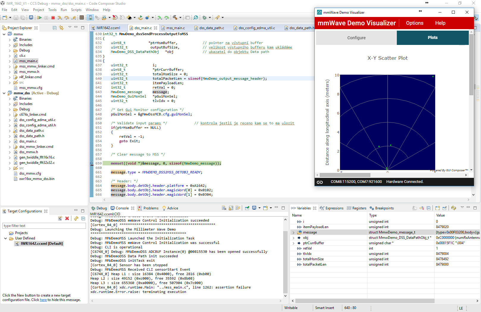
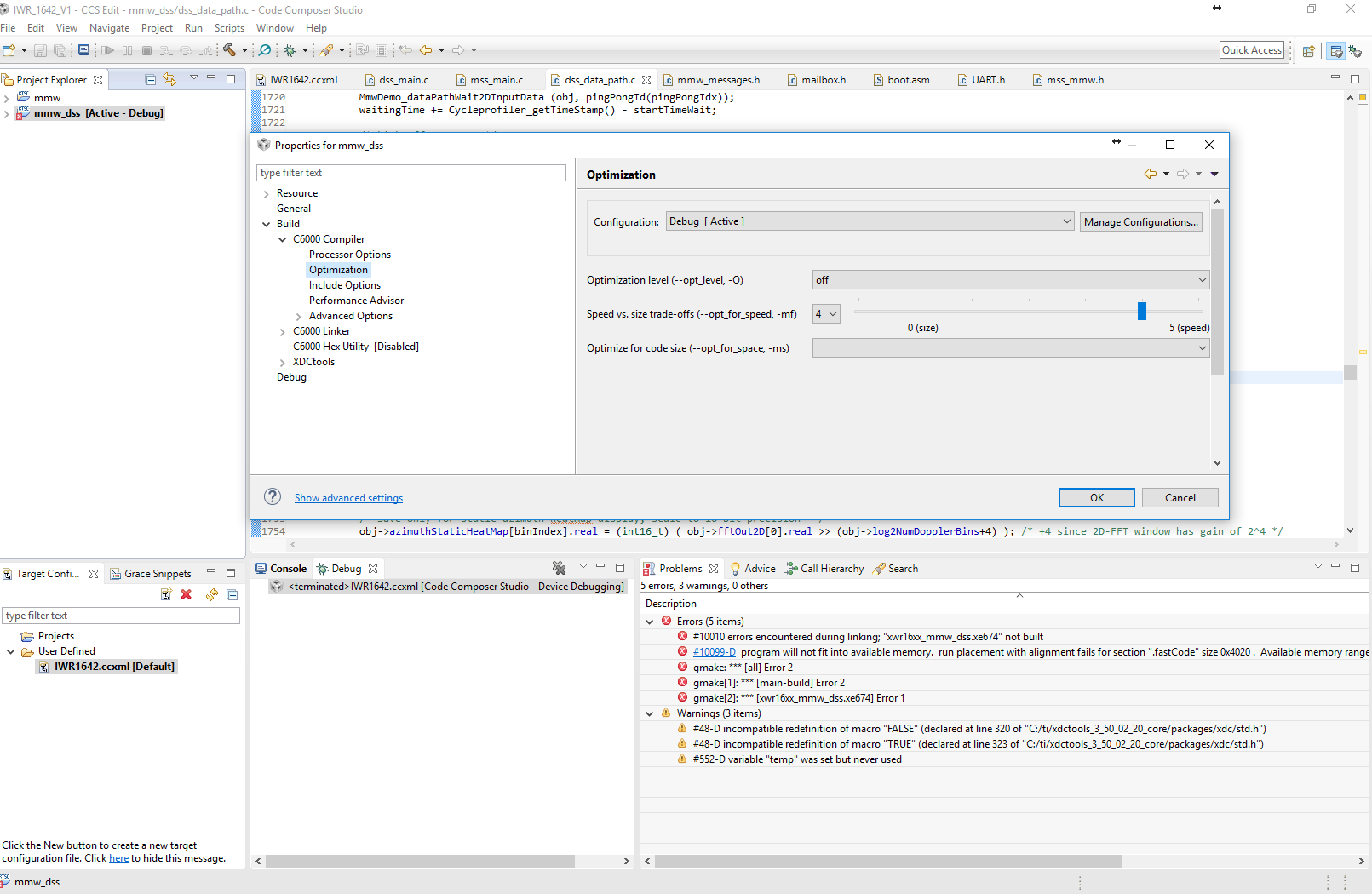
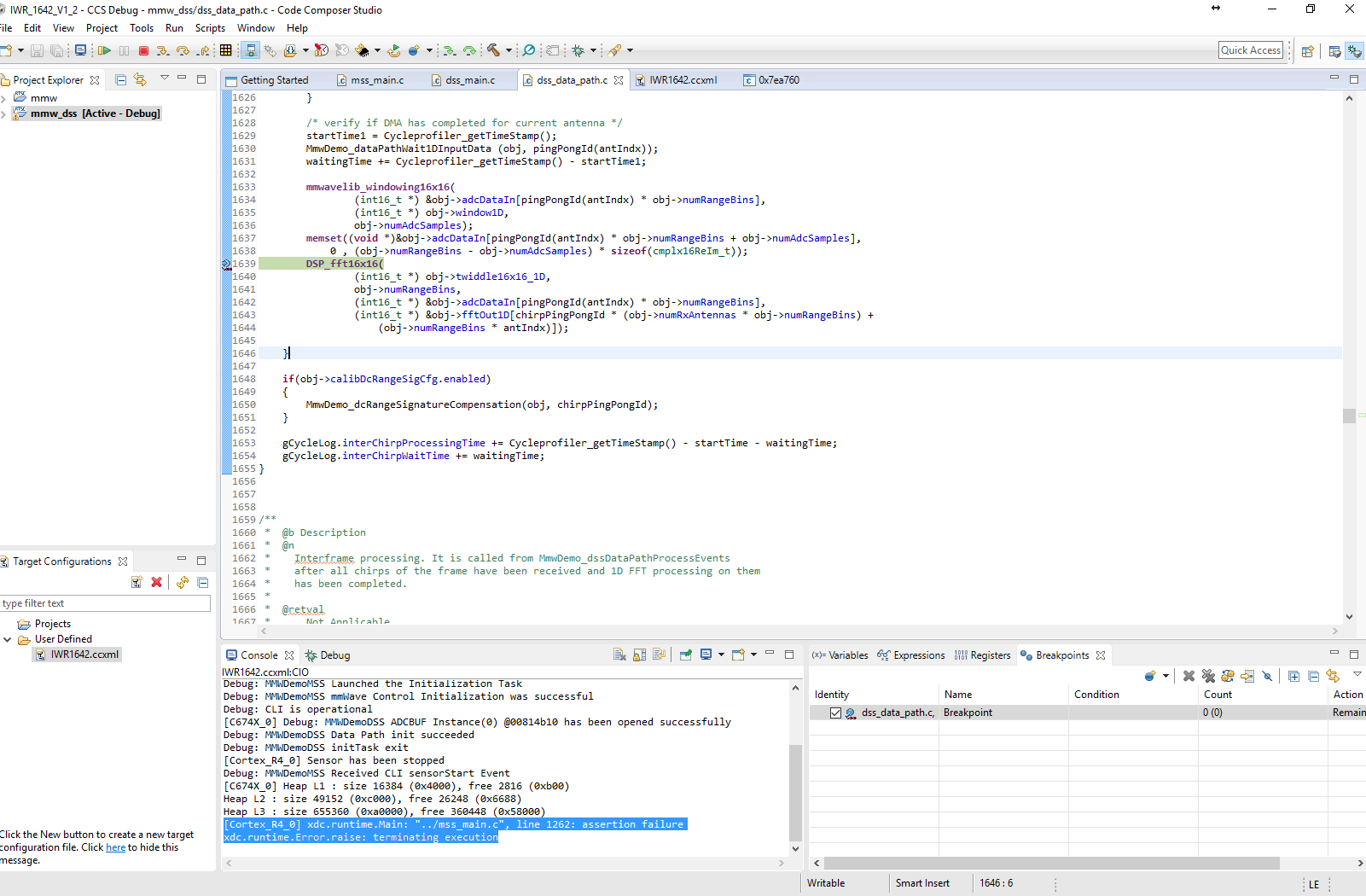
I need develope  signal processing chain for processing data after 2D fft. The freqvency spectrum and targets parameters will be analyse (using matlab) for this sensor and we will use own detection algorithm. I have problem how to read I/Q data or 2D freqvency spectrum using UART without some next external board. I understand then the reading using UART is too slow but it does not matter. Is exist some example how to adjust example from mmWave SDK?

Thank you Michal

  • Hi Michal,

    I'm guessing that you're running the mmw demo for IWR1642 with the 1.0.0.5 mmWave SDK. Is your question how to adjust the baud rate of the data UART, or the format of the data?

    -dave
  • Hello, not only. 

    I'm interest about modify example mmW from SDK (C:\ti\mmwave_sdk_01_00_00_05\packages\ti\demo\xwr16xx\mmw\docs\doxygen\html) to read 2D range/doppler matrix after 2D fft. I'm study the exampel code ant it is realy complicated project. I'm undersend then data after ADC are stored in buufer and transfered to L3? by EDMA for each chirp separately. After ADC conversion is called MmwDemo_interChirpProcessing for processing each chirp by 1D fft and save data to L3. I'm don't understand how is work second MmwDemo_interFrameProcessing part. Is data readed from L3 and procesed by second fft for computation doppler shift and save back in L3?

    WHEN is it true, is exist some example for reading this range/doppler matrix using UART?

    Michal

  • Hi Michal,

    I would suggest looking at the the mmw demo's html documentation.  Double click on C:\ti\mmwave_sdk_01_00_00_05\packages\ti\demo\xwr16xx\mmw\docs\doxygen\html\index.html. This should not only help you correlate processing steps to code functions, it will show you the format of the data that is currently output to the data UART port.

    The ADC data is DMA'd back and forth between the "radar cube" internal memory and L3 at various points through the processing stream (using EDMA).  This is also described in the html documentation.

    But to your original question, you don't need an external board, just a PC of some kind to host a serial terminal program such as TeraTerm.  If you want to output something other than what is currently output, you will of course have to modify the output structure for your needs.

     -dave

  • Hello Dave,


    thank you for your advice. I know about this manual and I read it, but when I see the void MmwDemo_interFrameProcessing(MmwDemo_DSS_DataPathObj *obj) function, the first is

    read data from L3 RAM by DMA
    and:
    windowing
    DFT
    log2Abs32

    and it is last instruction of processing data from one range and after that is start detection CFAR and some as easy tracker. This data from detection is saved by EDMA to L3 RAM.


    but where is instruction for send data to range/doppler matrix in RAM? Because data are buffered only for each range for doppler FFT and computation abs values by log2Abs32? (save log2Abs to L3 for each ranges)

    Michal
  • Hello,

    I have one next question.

    I tried "step" the program (IWR1642BOOT only SOP0 is selected - connected) but i have problem because program is falding down.

    Do you know where can be problem?

    thank you very much Michal

  • It is likely to be that the chirp parameters are not consistent, so the demo code is throwing an assert() to point you to the fact that something is wrong.  If you haven't already,  you can check your chirp in the Sensing Estimator:  

    https://dev.ti.com/gallery/view/1792614/mmWaveSensingEstimator/

  • Hello,

    the chirp parameters was set using mmWave Demo Visualizer - Configure corectly. I used send config to mmwave device.  I selected window plot after that. The all worked properly and when a tried add HW breakpoint do some line in mss_main for example send data using uart, the system is stopped without problem. The debug is failed when i set breakpoit to line witch made send data using MmwDemo_dssDataPathOutputLogging in dss_main.c. :(

  • A hardware or software breakpoint? Are you setting the breakpoint by double-clicking clicking to the left of the desired line? I have never heard of an issue simply setting a normal (sw) breakpoint. You may want to check your compiler options (-Ox) to make sure you have disabled optimizations and that -g is present.
  • Good morning,

    I'm always use the SW breakpoints. The compiler was set to 2-Global Optimization (it was default for both MSS and DSS). I tried use optimization level set to off. It worked for mss wher is sufficient memory, but for DSS is jumped error:

    Is exist some app.Note where is better description the code hierarchy? I cand find how is solved comunication betwen PC and RADAR by UART. The problem is i cand find where is readind received words for set parameters chirp.

    I'm not sure when is measured data send to MSS by MmwDemo_dssDataPathOutputLogging ... and when is this done is calend part  case MMWDEMO_DSS2MSS_DETOBJ_READY in MmwDemo_mboxReadTask for send data to PC by UART.

    The code hiararchy is realy marginally described in C:\ti\mmwave_sdk_01_00_00_05\packages\ti\demo\xwr16xx\capture\docs\doxygen\html

    Thank you for your time.

    Regards

    Michal

  • In dss\dss_data_path.c, line 1690 (function MmwDemo_interFrameProcessing()) is where the 2D FFT is performed. The outputs are stored in obj->fftOut2D.
  • but it is data from ADCbuffer saved for signal processing in L3 ram....but I'm funding where is reading function for UART buffer after received data from PC for seting chirp configuration.


    Do you some idea why isn't properly work the debugger?

  • I'm getting a bit tangled up in your text, but I think you're looking for where the data is output to the UART?  A few simple searches yielded:

    MmwDemo_dssDataPathProcessEvents(), in the case of MMWDEMO_CHIRP_EVT, calls MmwDemo_interFrameProcessing() where the 2D FFT is created.  It then calls MmwDemo_dssDataPathOutputLogging() which in turn calls MmwDemo_dssSendProcessOutputToMSS().  MmwDemo_dssSendProcessOutputToMSS() creates the output structure and sends it to MSS via the DSS->MSS mailbox.

    The MSS application then picks it up from the mailbox.  See function MmwDemo_mboxReadTask().  In the case of MMWDEMO_DSS2MSS_DETOBJ_READY, it makes several calls to UART_writePolling() to send the data.

    So - you will need to modify MmwDemo_mboxReadTask() in the MSS app, and MmwDemo_dssSendProcessOutputToMSS() in the DSS app to fill your new structure and send it the UART.

  • Perfect i interest aubout:

    So - you will need to modify MmwDemo_mboxReadTask() in the MSS app, and MmwDemo_dssSendProcessOutputToMSS() in the DSS app to fill your new structure and send it the UART.

    thank you...

    and do you have some idea why is not properly work debugger?

  • >and do you have some idea why is not properly work debugger?

    Two ideas:

    1) When you run an IWR1642 application in CCS, you must load and run *both* MSS and DSS executables, since they communicate with each other.
    2) The application may be compiled with -O3 optimization, which makes code stepping erratic at best, and may not allow breakpoints.
  • 1) Yes, I'm doing it because it was described in user guide in CCS for mmWsensor

    2) I switched optimization to O1 for both mmw and mmw_dss but result is same. when I get breakpoint do dss_data path the Console is write:

    [Cortex_R4_0] xdc.runtime.Main: "../mss_main.c", line 1262: assertion failure
    xdc.runtime.Error.raise: terminating execution

    and after step to next line 

  • If you will notice, you've set a DSS breakpoint, but it's MSS' main that is throwing the assert - presumably since the DSS is no longer communicating with it. This should only be a problem if you plan to try to resume execution, which you probably can't unless you set breakpoints in corresponding points in both MSS and DSS.