This thread has been locked.

If you have a related question, please click the "Ask a related question" button in the top right corner. The newly created question will be automatically linked to this question.

OPT8241-CDK-EVM: OPT8241-CDK-EVM : Voxel Viewer calibration problem

Part Number: OPT8241-CDK-EVM

Hi,

I purchased OPT8241-CDK-EVM in August, 2017.

I have some questions when i'm doing the calibration on Voxel Viewer.

I follow the Voxel Viewer user guide and do the calibration step-by-step.

Here's my questions:

1) What does "Frequency Calibration" calibrate for?  How do i set the parameter, "Expected Modulation Frequency"?

2) What does "Non-linearity Calibration" calibrate for? I can measure <Actual Distance>, but how can i measure <Phase1> and <Phase2>?

3) Is there any examples for those two calibrations?

4) I see the "Calibration issues" in the document.

    Frequency calibration is not performed on the boards.

    Non-linearity calibration is not performed in the boards.

    What does that mean?

Look forward to your answers.

Thanks & Regards.

Peter

  • Hi Peter,  please see this video which should answer yous rquestions.

  • Hi Larry,

    Thanks for your reply. The video which you posted  is very detailed and helpful.

    But i still have some problems when i am doing my calibration.

    Frequency Calibration:

    In your slide page 5, it said i can measure the "Actual Frequency" at the "ILLUM_EN_P pin of 3D-TOF sensor".

    Where can i find this "ILLUM_EN_P pin"?  Using Voxel Viewer or i need to export from the board?

    Non-linearity Calibration:

    In slide page 9, you gave an example.

    mod_freq1 = 50MHz, selected period of 90 degrees, umambiguous range = 3m, 90 degrees corresponds to 75 cm, each entry's delta distance is 4.7 cm.

    My calibration is as follows:

    Step1. Find a wall, and put my device in the position which is nearest to the wall without saturation, and record distance & phase_near.

    Step2. Move my device > 75 cm from the wall.

    Step3. Then i move my device 4.7 cm toward the wall, and record the distance & phase. Move 4.7 cm and record again and again.

    Is that right? I can measure the distance from the wall easily. But how can i get the phase1 and phase2 values?

    Look forward to your reply.

    Thanks & Best regards!

    Peter

  • Peter,

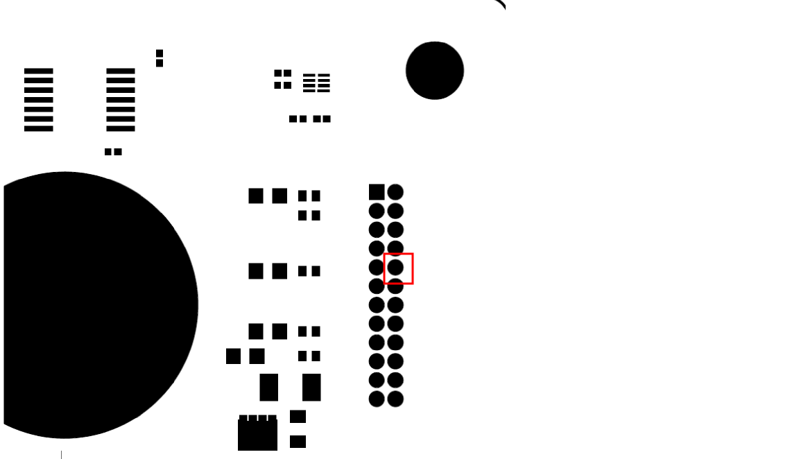
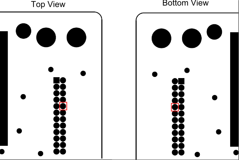
    You need to check on ILLUM_P (not ILLUM_EN_P). It is available on the connector connecting the illumination board to the sensor board. 

    This is where you will find it on the illum board (Top side, J1, pin 10): 

    This is where you will find it on the sensor board (Bottom side, J1, pin 10): 

    Since we use an accurate crystal on board, frequency calibration can be skipped. Other errors will be more dominant.

    Regards

  • Peter,

    For non-linearity calibration, multiple readings will be needed. At the least 10 distances within quarter of a range will be nice to have.
    I have requested another engineer for a detailed explanation.

    Regards
    Bharath
  • Hi Bharath,

    Thank you for your attention in this matter, and i am looking forward to your comments for non-linearity calibration.

    Best regards
    Peter
  • Hi Bharath,

    Thanks for your detailed explanation.

    For your suggestion, when i am doing my calibration, i just skip the frequency calibration, right?
    But if i really want to know the "actual frequency" value, i have to use the oscilloscope to measure the signal from ILLUM_P(J1, pin 10), right?
    Is there any easier way to get the actual frequency value?

    Although i know that i just skip this step when i am doing the calibration, i still want to know how to measure this frequency value.
    Looking forward to the reply, thank you!

    Best regards,
    Peter
  • Hi Peter,

    You have to measure the frequency from the illim_p signal for frequency calibration - there's no other alternative. If the pin seems difficult to probe, you can also probe the R101 on OPT8241_CDK_EVM_SB.

    For non-linearity correction: Your method of moving the CDK back is correct. You need not move it in steps of 4.7 cm, though. Ten different readings will be sufficient.

    It seems that you're using just a single frequency for calibration (50 MHz). In such a case, you do not need phase 1 and phase 2 data. Just phase 1 data will be sufficient. In the Calibration Wizard from Voxel Viewer, use <Actual Distance> and <Phase 1> only.

    For a single frequency, phase 1 can be obtained by checking the phase value at the given distance at (cx, cy) obtained from lens calibration. You can get the phase value from Voxel Viewer.

    If you want to use de-aliasing, two frequencies will be required, and hence two phases. In such a case, in VoxelViewer, for getting phase 1 and phase 2, use the following steps:

    1) Set ind_freq_data_en = true

    2) Get the phase of the cx, cy point (obtained from lens calibration). To get phase data for first modulation frequency, set ind_freq_data_en to False. To get the second modulation frequency phase data, set ind_freq_data_en to True to get phase 2 data.

    3) Repeat this for each distance.

  • Hi Suramya,

    Thank you for your clear explanation. It's very helpful.

    Best regards,
    Peter