Because of the Thanksgiving holiday in the U.S., TI E2E™ design support forum responses may be delayed from November 25 through December 2. Thank you for your patience.

This thread has been locked.

If you have a related question, please click the "Ask a related question" button in the top right corner. The newly created question will be automatically linked to this question.

Active shielding not working.

Other Parts Discussed in Thread: FDC2214EVM, TLV3544, FDC1004, FDC2214

Hi, I'm using the FDC2214EVM board for a capacitive sensing application where i need to use active shielding. I'm using the TLV3544 as a buffer but is not having the desired effect. 

https://e2e.ti.com/support/sensor/capacitive-sensing/f/987/t/486054?tisearch=e2e-quicksearch&keymatch=fdc2114%20activ

I read on this thread that it doesn't work "as optimal" as it should. I wonder why TI would put the active shielding option on the datasheet if it does not work well. 

What can i do to improve the active shield performance? 

Thanks.

  • Hello,
    For active shield applications I would recommend the FDC1004 device which has the shield drivers integrated to the device. For the FDC2214 we would recommend a simple passive shield by using a ground plane beneath the sensor. You can use a hatched pattern instead of a solid fill for improved sensitivity.
    Regards,
    Luke
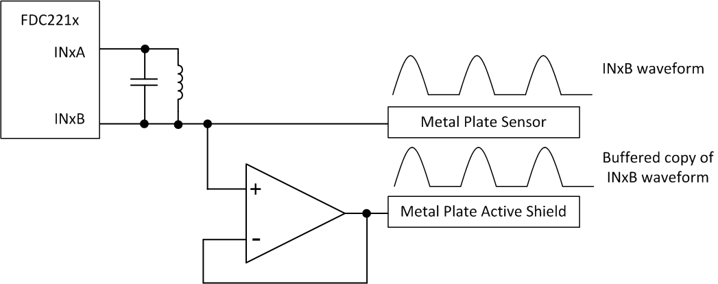
  • Hi additionally  if you are trying to use  an external amplifier to create an active shield this can work, but it comes with some design challenges. Fundamentally you can shield the sensor with an actively driven plate like shown below:

    The key to getting this technique to work is to ensure that both the shield and the sensor are in the same phase so that there is no potential difference between them and hence no capacitance shift seen by the sensor. This means that you may require a high bandwidth amplifier with minimal distortion and small propagation delay. Additionally you will likely need to operate the amplifier on a split supply or ensure that the output stage is rail-to-rail to avoid saturation and distortion effects. From the sensor side, you may also have to use a lower sensor frequency (higher inductance) to minimize the effect of phase delay. If you have tried this configuration and are not getting a working sensor than we would like more information such as waveform captures of both sensor and shield simultaneously, sensor configuration, device settings, and raw data from the FDC221x.

    Thanks!

    Luke