This thread has been locked.

If you have a related question, please click the "Ask a related question" button in the top right corner. The newly created question will be automatically linked to this question.

LDC1000EVM: Does not work homemade sensor

Part Number: LDC1000EVM
Other Parts Discussed in Thread: LDC1101

Hello!

I made a sensor, about 220 turns with a 0.2 mm wire, a winding diameter of about 1.5 cm. I chose the frequency below to see the difference between ferrous metals and non-ferrous metals.
Measuring the RLC-meter separately the coil and the capacitor and received the following data:
L = 1235 μH
Resistance DCR (on a direct current) = 9,4 Ohm
C = 8.9 nF
The calculated and mesured resonance frequency was about 48 kHz.
Measured at the resonance frequency, the resistance of the circuit Rp was 8 kΩ.
Acted according to the instruction (slyw022):
1. I broke the factory coil from the board
2. Measured L handmade coil
3. Measured C
4. Calculated and measured the resonant frequency, it was 48 kHz, which falls in the range from 5 kHz to 5 MHz
5. On the oscilloscope and the oscillator according to the instruction (method 3 in snoa936, measured Rp was 8 kΩ (Rs about 15-17 Ohm), which falls in the range from 0.798 kΩ to 3926.991 kΩ
6. Updated the capacitor readings in the program.
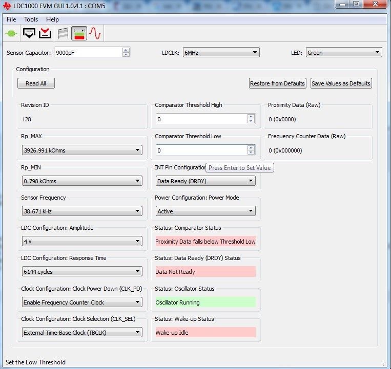
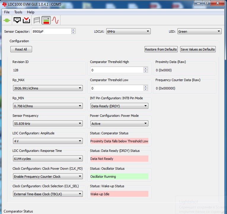
7. I chose the sensor frequency 20% lower, i.e. about 38 kHz (attached)
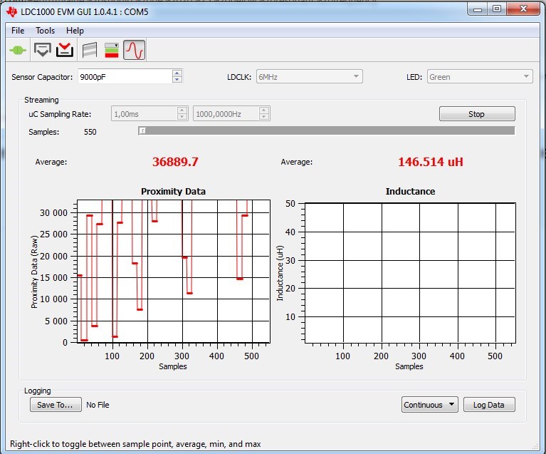
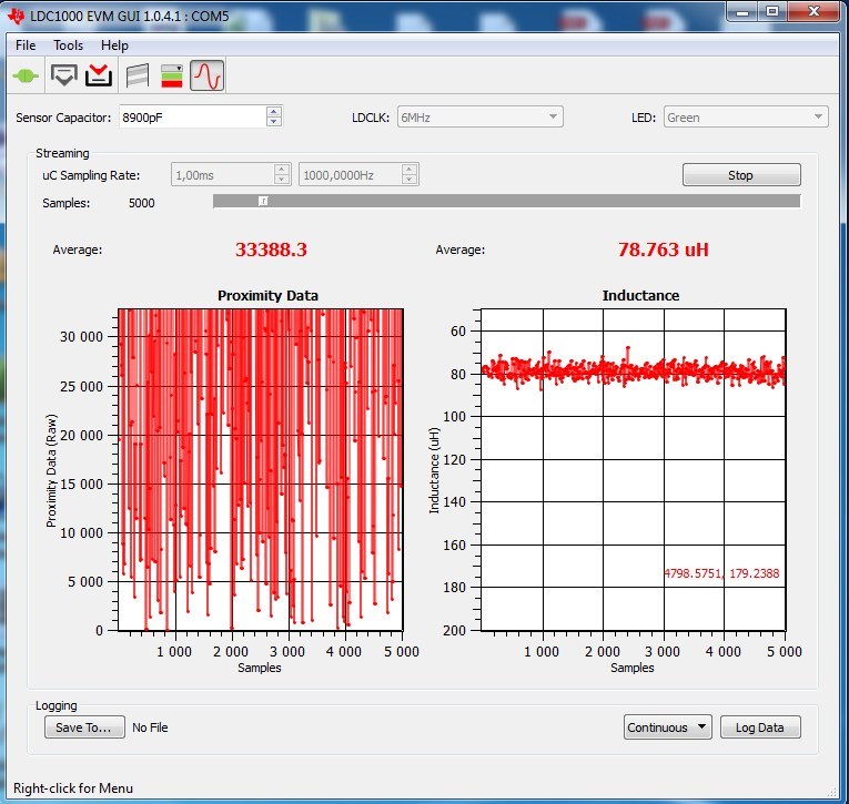
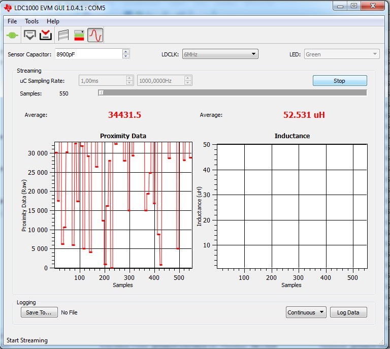
8. When I pressed "Start", then I have a proximity data that goes off scale! (see attached images)

Why does this happen and what did I do wrong?

  • Hi Victor,

    It looks like the sensor is oscillating, as you are getting an inductance measurement. Did you set the CFB filter capacitor value? Refer to section 8.1.3 of the datasheet for instructions on how to do that. The value of CFB needs to be set for each sensor design. Also, the CFB cap is a function of the RPMIN and RPMAX settings.

    Once you adjust the CFB cap, take a look at the sensor signal with an oscilloscope to see if there is a saw-tooth modulation on the sensor (refer to figure 4 of www.ti.com/.../snaa221a.pdf; note that Figure 4 is a differential trace; if you look INA or INB to ground, the signal will be half-rectified).

    Regards,

    ChrisO
  • Very thank's!
    Ok, i will try.
    Explain, what is the function of the capacitor CFB, and how does its magnitude affect the triangular process?
  • Hi Victor,

    The CFB sets an internal filter which is needed for correct operation.

    Regards,

    ChrisO
  • What signal does it filter?
    Or does he set the period in the rise and fall time of the triangular modulation?
  • Hi Victor,

    It filters an internal feedback loop that controls the triangle modulation.

    Regards,

    ChrisO

  • Hello!

    I soloed the CFB capacitor, it turned out 680 pF. But still, in the program the value of the proximity data goes off scale.

    Help me figure out what's wrong.

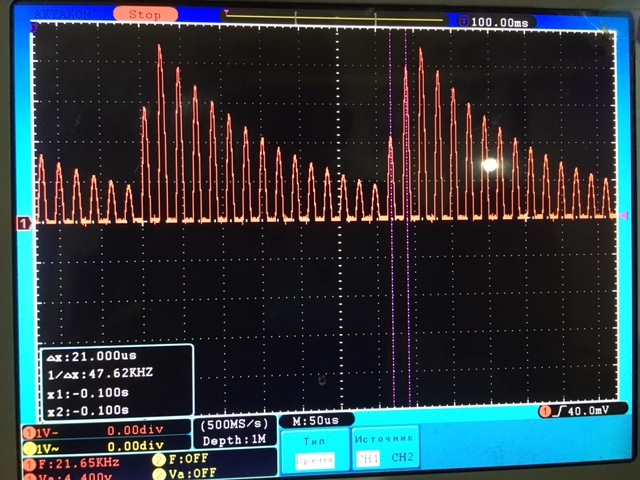
    Occillation on LC tank, 1 pin oscilloscope on ground, 2 pin - on pin LC tank 

    Natural frequency = 47.62 kHz

    Voltage on CFB pin (added capacitor 680 pF) across 1kOhm resistor on oscilloscope pin:

  • Hi Victor,

    Please clarify how did you probe the CFB node with the scope? The way you described the measurement is a bit ambiguous. Refer to the picture below:

    The sensor scope trace looks good. Can you get a scope trace of the CFB trace showing about 2ms/div?

    Regards,

    ChrisO

  • Hello!

    I correctly connected the oscilloscope. Oscillogram is the same as I mentioned earlier.
    I made a video for you.

    www.youtube.com/watch

    If you can not see it, you will say, I took photos.

  • Hi Victor,

    Thank you, the video was very helpful. I was pretty sure that you were doing things correctly, but I needed to confirm that.

    I don't see anything wrong with your settings or process - you have found a tricky problem here. I have only a few things to check:
    1) Please try to use a lower RPMAX setting (such as 981.7k); you will need to make sure that the CFB cap signal amplitude is still around 1.0Vpp.

    2) If you still have the original EVM sensor, please see if that works with the original value CFB cap.

    3) Do you have access to a VNA or impedance analyzer? I would like to understand your sensor better. It looks like your sensor is an air core, correct?

    When you say the wire is 0.2mm, is that diameter or area?

    Regards,

    ChrisO

  • Hello, ChrisO!

    1. Set Rp_max = 981.7 kOhm, the peak-peak voltage on the CFB 1V, the proximity is off scale (see in the video).
    2. The original sensor works well (see video).
    3. I do not have an impedance analyzer, but there is a RLC meter. With the help of an oscilloscope I measured the resonant frequency and the resistance active at the resonant frequency. Results of measurements in my first post. The coil has an air core - look at the video.
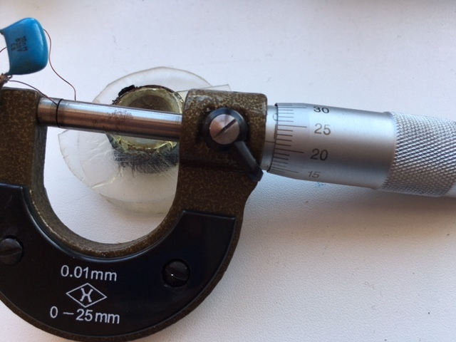
    4. Wire diameter (not area, area measure in mm^2) with insulation 0.21-0.22 mm, without insulation - about 0.2 mm, see the photo below:

    When there was a problem, I noticed that the sensor does not measure the inductance correctly.

    I started solving this problem as follows:

    When I measured the oscillation frequency on the INA in the INB, 47 kHz was obtained.
    Considering paragraph 7.3.3 of the datasheet:

    I calculated that for Fsensor = 47 kHz, for RESPONSE_TIME = 6144 and Fext = 6 MHz, the Fcount should be:

    f = (6 000 000 * 6144) / (3 * 47 000) = 261 000

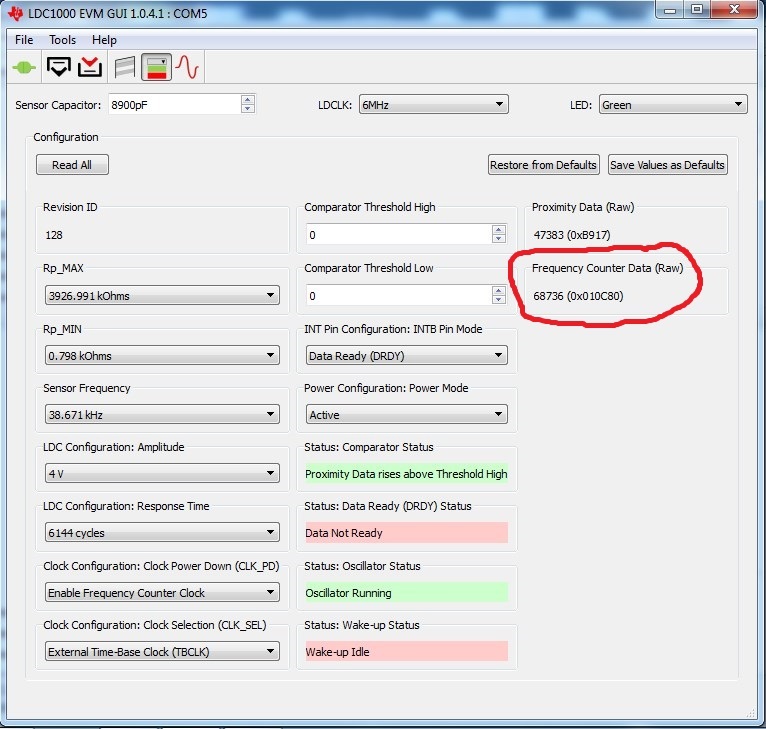
    But in our measurements (when you press the "Read All" button) was only 68736 !:

    I began to change the values ​​of Rp_min and Rp_max so that the value of Fcount was near to the calculated value of 261,000, and I achieved at 7.14 kΩ for Rp_min, and Rp_max for almost any, but not less than 7.182.

    At these values, the inductance of the beginning is measured more correctly (about 1100 μH, see video), but:
    1) there is still interference (see video) and the proximity value is close to saturation;
    2) as soon as I bring the metal target to the coil, Proximity data off scale and lot of noise (see the video)/

    My video - see in HD 

    It got better, but the problem did not disappear.
    Your suggestions?

  • Hello Victor,

    Thank you for your patience in this matter. From the tests you did, it is clear that there is no problem when the EVM default sensor is used, or your PC and GUI; there is either something unusual with your sensor or there is some interaction with the LDC1000 and your sensor.  Can you show the sensor waveform (either INA or INB) when the RPMAX is lowered?

    Perhaps there are some inter-coil shorts in your sensor which are producing an inconsistent current path.

    Regards,

    ChrisO

  • Hello!

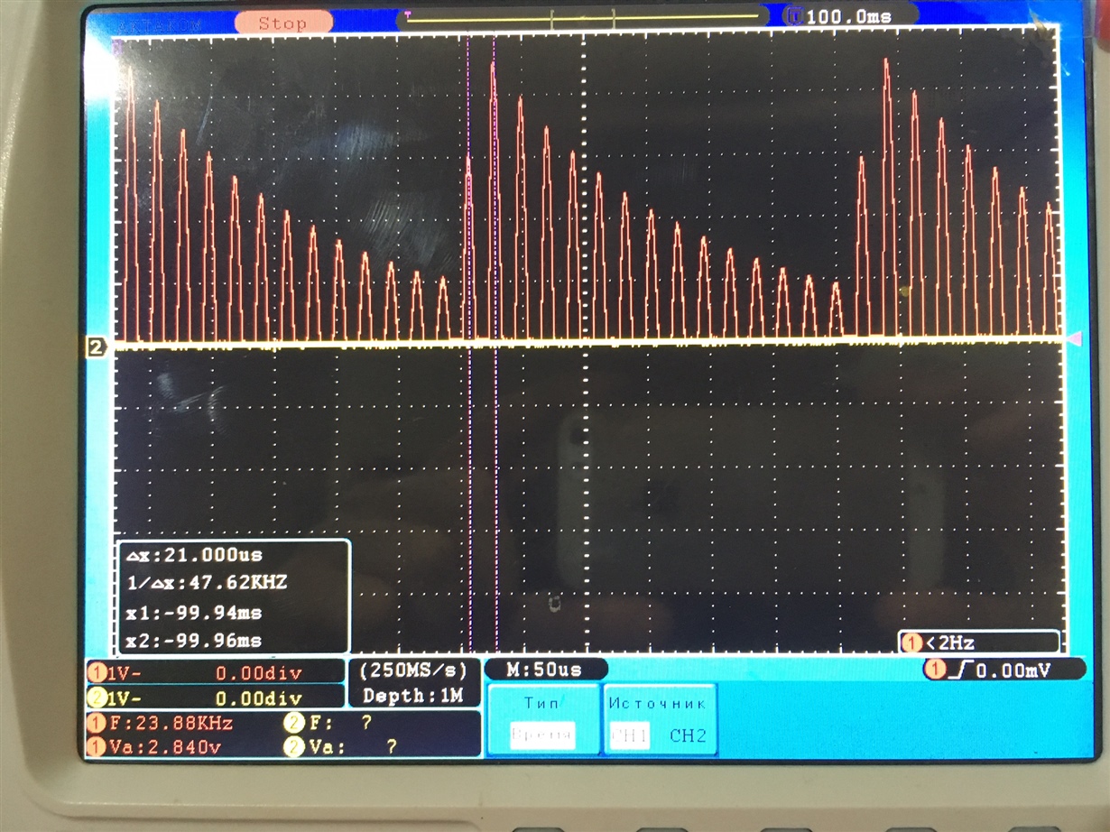
    Oscillogramm voltage between INA (INB) when Rpmin=0.798 kOhm Rpmax=3926.991 kOhm:

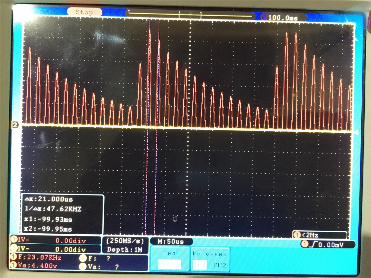
    Oscillogramm voltage when Rpmin=0.798 kOhm Rpmax=981.784 kOhm

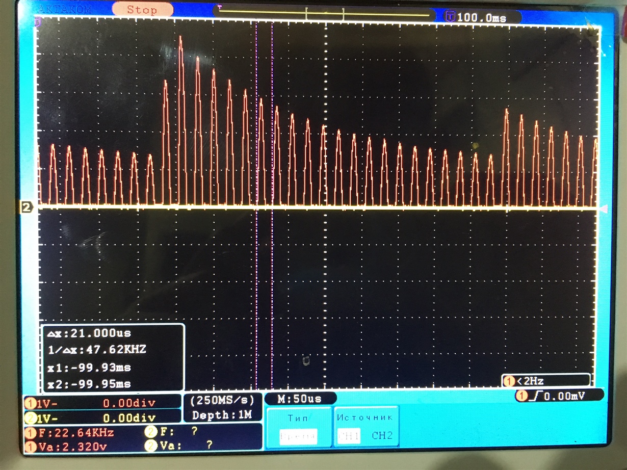
    Oscillogramm voltage when Rpmin=0.798 kOhm Rpmax=16.16 KOhm

    And also:

  • Hi Victor,

    That last oscilloscope trace you provided was very helpful; I am wondering if the watchdog is not set properly. Please try reduce setting for the watchdog frequency (the GUI field sensor frequency) to <10KHz.

    Also, try using a larger value for the RPMIN setting - please try RPMIN set to ~3K. Please make sure that the CFB signal has the correct amplitude, as you have done previously. I would like to reduce the slope on the rising edge of the sensor signal.

    Please provide a scope picture of the new the sensor signal on the longer timescale (like the last picture you provided).

    Regards,

    ChrisO
  • Hello, Chris!

    I did the following:

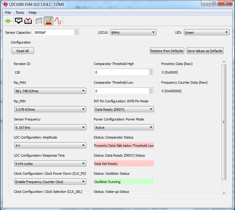
    1. GUI sensor frequency = 9.197 kHz

    2. Rp_min=3.078 kOhms

    And also:

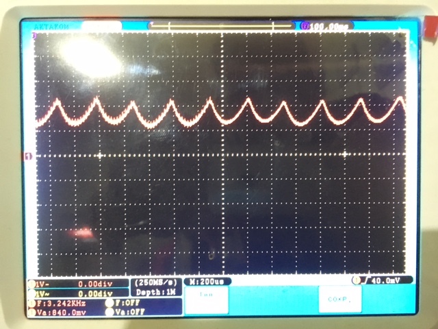
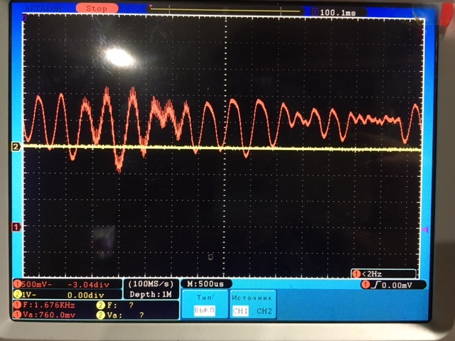
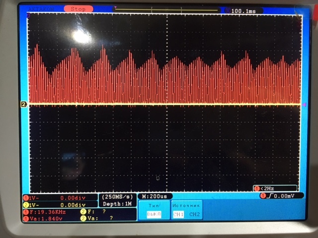
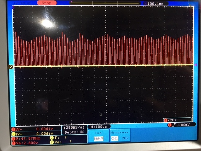
    Now the oscillogram of the CFB via a 1 kOhm resistor:

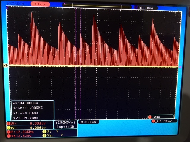
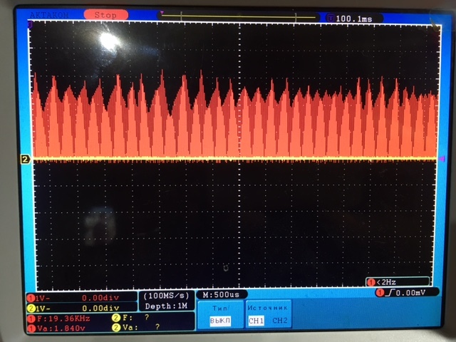
    Now the oscillogram of the INA (INB):

    Why, when solving a problem, do you pay attention to Frequency Counter Data (RAW)?

    Before that, I was creating a post, but I did not get an explanation of the principles of LDC functioning.
    Chris, I have a huge request for you.
    When you ask for anything (for example, reduce Rp_min or increase the slope), explain, please, as it Influence on process of work LDC. For example, how will the change in Rp max or Rp min affect the slope of oscillation process on the INA?
    If you explain to me in the course of our dialogue, and I'll try to understand, we will solve the problem faster and our cooperation will be more fruitful.
    Thank you.

  • Hello Viktor,

    My apologies on not giving you the guiding principles behind the device. We do have several application notes - refer to www.ti.com/.../getliterature.tsp, for example.

    The LDC1000 (and LDC1101) alternates between two currents into the sensor - when driving RPMIN (which must be less than the actual device sensor RP), the device injects more current than is needed into the circuit, so the sensor voltage increases. Using a lower RPMIN (and hence, a larger current) will add energy into the sensor faster, and so the voltage in the sensor will increase faster (which corresponds to the slope of the rising edge).

    Once the amplitude hits the peak value, the LDC1000 drives a low current, corresponding to RPMAX. A higher value for RPMAX injects less current into the sensor, and so the amplitude drops off faster.

    The CFB is a filter capacitor which is used to help the device select between the drive currents.

    The LDC measures the inductance by counting a fixed number of sensor cycles (e.g., when set to 6144, the device counts 2048 cycles of the sensor). The number of cycles of the reference frequency for the programmed number of sensor cycles is the ODR, and can be used to calculate the sensor frequency, and therefore the inductance.

    The Sensor frequency setting configures the watchdog timer; if the sensor oscillation is not observed within the watchdog timer, the LDC does the only thing it really can - attempt to 'kickstart' the sensor by injecting a pulse of current; that can help the sensor start oscillating.

    I believe there is something strange with your sensor - perhaps there are some shorts in the wire windings or something else.

    Regards,
    ChrisO
  • Thanks for the clarification, Chris!

    The concept of principles was necessary for correct adjustment and construction of sensors, and not for commercial purposes.

    If you are interested in this problem then you can make the same sensor and see the problem.

    The problem is not a solution, where are we moving on?