This thread has been locked.

If you have a related question, please click the "Ask a related question" button in the top right corner. The newly created question will be automatically linked to this question.

IWR1642: Simultaneous measurement of elevation, azimuth and high velocity with a precise resolution using IWR1642

Part Number: IWR1642
Other Parts Discussed in Thread: IWR1443, TIDEP-0094, MMWAVE-DFP

Hello

We are designing mmWave Radar system with a capability that can estimate a high speed, azimuth and elevation simulataneouly.

The chip considered is IWR1642. In the IWR1642 EVM, only azimuth can be estimated because all the antennas are aligned horizontally.

In the IWR1443EVM, the elevation and azimuth can be estimated using three tx antennas (two antennas aligned horizontally and the one vertically)

and TDM or BPM MIMO techinque.

According to the above conclusions, I thought that IWR1642 chip also can be used in estimating the elevation and azimuth at the same time

by changing the array of two Tx antennas like IWR1443.


The questions I'd like to clarify are right below.


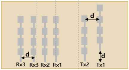
1. Is it possible to estimate the elevation and azimuth simultaneously using like the figure below.


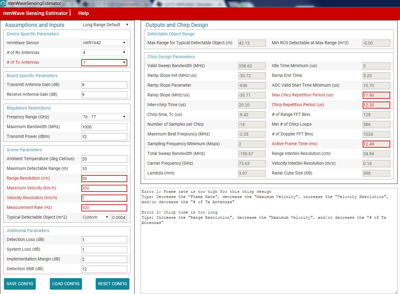
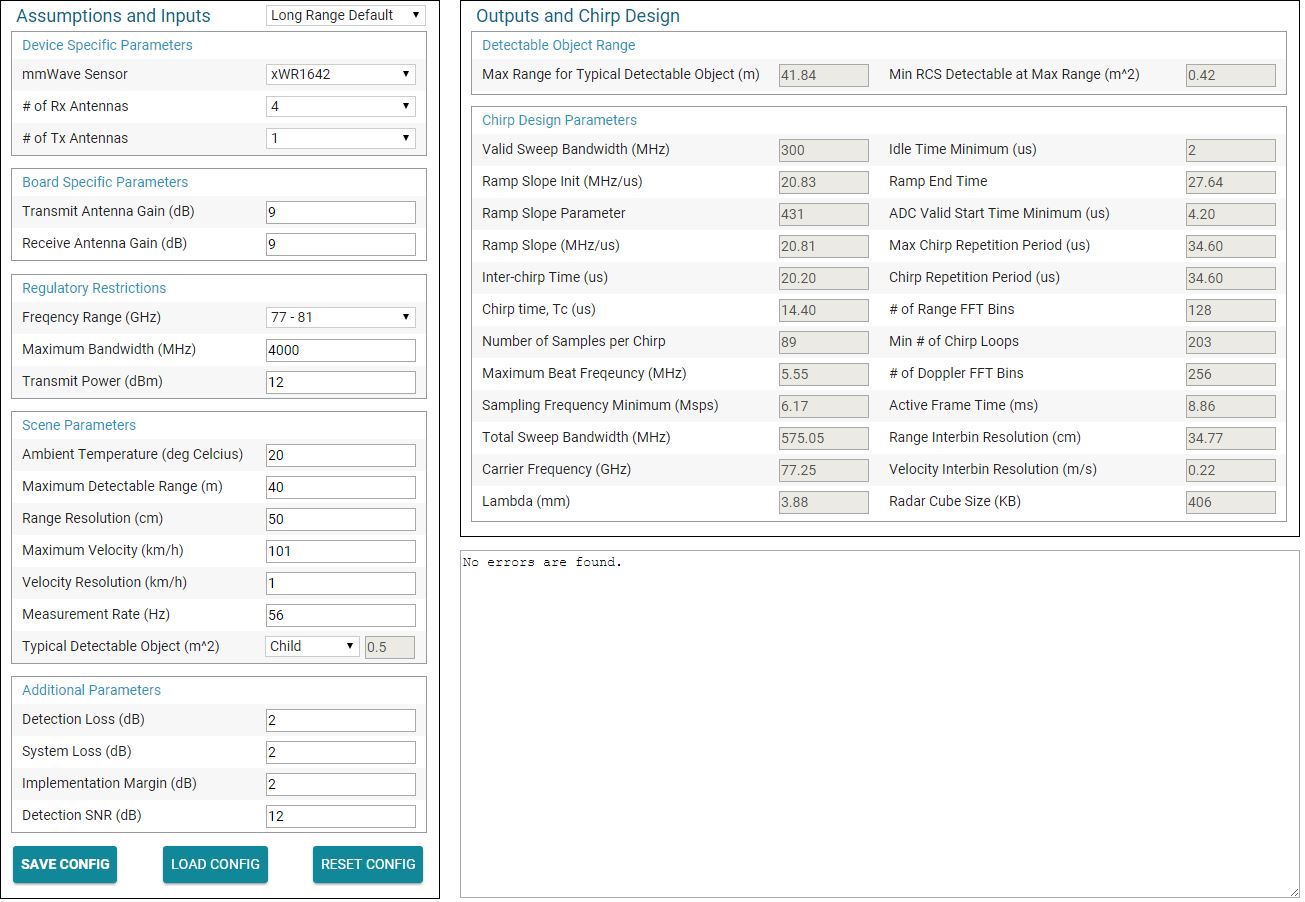
2. In the mmWave Demo, I couldn't get the speed above 200km/h with any configuration. If I use BPM MIMO technique,

Could I get the speed above 200km/h(with a resolution of 1km/h or below) and azimuth and elevation?

Thank you for your assistance.

  • {
        "platform": "xWR1642",
        "num_rx": 4,
        "num_tx": 1,
        "tx_gain": 8,
        "rx_gain": 8,
        "frequency_range": "77 - 81",
        "maximum_bandwidth": 4000,
        "tx_power": 12,
        "ambient_temperature_degC": 20,
        "maximum_detectable_range": 40,
        "range_resolution": 49,
        "maximum_velocity_kmph": 99,
        "velocity_resolution_kmph": 1,
        "measurement_rate": 5,
        "typical_detected_object": "Adult",
        "detection_loss": 2,
        "system_loss": 2,
        "implementation_margin": 2,
        "detection_SNR": 12,
        "maximum_radar_cube_size": 640,
        "maximum_RF_bandwidth": 5,
        "maximum_sampling_frequency": 6.25,
        "sensor_maximum_bandwidth": 4000,
        "maximum_allowed_bandwidth": 4000,
        "starting_frequency": 77,
        "maximum_velocity": 27.5,
        "velocity_resolution": 0.2777777777777778,
        "idle_time": 7,
        "adc_valid_start_time": 12.2,
        "excess_ramping_time": 1,
        "periodicity": 200,
        "ambient_temperature": 293.15,
        "noise_figure": 16,
        "num_virtual_rx": 4,
        "non_coherent_combining_loss": 2,
        "rcs_value": 1,
        "combined_factor_in_dB": -8,
        "combined_factor_linear": 0.15848931924611134,
        "valid_sweep_bandwidth": 306.1224489795918,
        "inter_chirp_time": 20.2,
        "aux_comp_coeff_a": 77153061224.48979,
        "aux_comp_coeff_b": -1165046.196660482,
        "chirp_time": 15.100453282995273,
        "ramp_slope_init": 20.272401314225345,
        "ramp_slope_parameter": 420,
        "ramp_slope": 20.27750015258789,
        "aux_comp_T1": 1,
        "maximum_beat_frequency": 5.4073333740234375,
        "sampling_frequency": 6.008148193359375,
        "number_of_samples_per_chirp": 91,
        "total_sweep_bandwidth": 574.7880020141602,
        "idle_time_minimum": 2,
        "ramp_end_time": 28.34609777777778,
        "carrier_frequency": 77.24738710702078,
        "aux_comp_T2": 3.2,
        "adc_valid_start_time_2": 4.2,
        "lambda": 3.883626504859915,
        "max_chirp_repetition_period": 35.3,
        "chirp_repetition_period": 35.3,
        "num_range_fft_bins": 128,
        "min_num_of_chirp_loops": 199,
        "max_range_for_typical_detectable_object": 44.65120752387842,
        "min_rcs_detectable_at_max_range": 0.644031534022743,
        "num_doppler_fft_bins": 256,
        "active_frame_time": 9.0368,
        "range_inter_bin_resolution": 34.8359375,
        "velocity_inter_bin_resolution": 0.21592881944444445,
        "radar_cube_size": 398
    }
    Hello,

    In the antenna depiction, you would can have  Tx2, Rx1-4 as Azimuth, and Tx1, Rx1-4 as Elevation.   if you use the BPM program feature for Tx1, you can have 180 degree phase shift, as you process the Rx1-4, you would have to load different  filters into the DSP to match filter receive the two different transmitters.   In the example, you can load the supplied json file into the Sensing Estimator , this has a range of 40meters, a max velocity of 99kmph.   There is a velocity extension algorithm with tracking to extend to ~200kmph.

    I will ask the System engineers for the experiment that has a code example of BPM decoding without TDM, it is not attached to this thread yet.  If I find an lab or experiment with code for 2 simultaneous transmit, I will reference it.

    You could do your initial experiment with an IWR1443using Tx1, Tx3.  Using the data capture demonstrating software, and then to capture the Receiver output.   Once you have the captured data, and code needed you will know if the IWR1642 can performn with the natenna

    You can download the Sensing Estimator from this TI link,

    40mrange_99kmph.json - Sensing Estimator configuration file

    - this report discusses using VMAX extension to double the velocity using a tracking and difference algorithm.

    Regards,

    Joe Quintal

  • Thank you Quintal.

    I'll try it. Have a nice weekend.

  • Hello, Quintal

    I have an additional more specific question about the maximum velocity we could achieve.

    I attach the configuration file obtained using mmWaveSensingEstimator.

    This configuration can obtain 300km/h and 1km/h resolution with a 1-tx /4rx antennas

    But I am not sure using this configuration can be used in simultaneous measurement of azim/elev angles.

    Is it possible to get max 300km/h while getting azimuth and elevation angles in IWR1642 chip with tx/rx antennta configration that I designed earlier.

    Of course, in here, I assume BPM MIMO radar technique is utilized.

    Thanks.

    Regards.iwr1642_300km_1km_angle_30d.zip

  •  Hello,

    When you use the Sensing Estimator, the boxes hilighted in red must be corrected to have a valid System parameter input, and chirp output.

    In the file you have sent,  I have included the JPEG of the Sensing Estimator with your JSON file.  Reworking your example,  considering Velocity extension (see mmwave SDK User Guide - extendedMaxVelocity, you can have a velocity extension of 2x.   

    The reworked Sensing Estimator configuration is also attached.  40meters, 99kmph, with VMax extension 2x 198kmph.   With modification of the VMax extension algorithm for each tracking Rx, you can extend the Nyquist multiplier.  TI's algorithm source is in the SDK for VMax of 2x.  

    {
        "platform": "xWR1642",
        "num_rx": 4,
        "num_tx": 1,
        "tx_gain": 9,
        "rx_gain": 9,
        "frequency_range": "77 - 81",
        "maximum_bandwidth": 4000,
        "tx_power": 12,
        "ambient_temperature_degC": 20,
        "maximum_detectable_range": 40,
        "range_resolution": 50,
        "maximum_velocity_kmph": 101,
        "velocity_resolution_kmph": 1,
        "measurement_rate": 56,
        "typical_detected_object": "Child",
        "detection_loss": 2,
        "system_loss": 2,
        "implementation_margin": 2,
        "detection_SNR": 12,
        "maximum_radar_cube_size": 640,
        "maximum_RF_bandwidth": 5,
        "maximum_sampling_frequency": 6.25,
        "sensor_maximum_bandwidth": 4000,
        "maximum_allowed_bandwidth": 4000,
        "starting_frequency": 77,
        "maximum_velocity": 28.055555555555557,
        "velocity_resolution": 0.2777777777777778,
        "valid_sweep_bandwidth": 300,
        "idle_time": 7,
        "adc_valid_start_time": 12.2,
        "excess_ramping_time": 1,
        "periodicity": 17.857142857142858,
        "ambient_temperature": 293.15,
        "noise_figure": 16,
        "num_virtual_rx": 4,
        "non_coherent_combining_loss": 2,
        "rcs_value": 0.5,
        "combined_factor_in_dB": -6,
        "combined_factor_linear": 0.251188643150958,
        "inter_chirp_time": 20.2,
        "aux_comp_coeff_a": 77150000000,
        "aux_comp_coeff_b": -1111177.3267326732,
        "chirp_time": 14.402816937558951,
        "ramp_slope_init": 20.82925869991966,
        "ramp_slope_parameter": 431,
        "ramp_slope": 20.80857753753662,
        "aux_comp_T1": 1,
        "maximum_beat_frequency": 5.548954010009766,
        "sampling_frequency": 6.165504455566406,
        "number_of_samples_per_chirp": 89,
        "total_sweep_bandwidth": 575.0482234954834,
        "idle_time_minimum": 2,
        "ramp_end_time": 27.635152977571536,
        "carrier_frequency": 77.25386625622585,
        "aux_comp_T2": 3.2,
        "adc_valid_start_time_2": 4.2,
        "lambda": 3.8833007917687636,
        "max_chirp_repetition_period": 34.6,
        "chirp_repetition_period": 34.6,
        "num_range_fft_bins": 128,
        "min_num_of_chirp_loops": 203,
        "max_range_for_typical_detectable_object": 41.839125766394716,
        "min_rcs_detectable_at_max_range": 0.4177145128041569,
        "num_doppler_fft_bins": 256,
        "active_frame_time": 8.8576,
        "range_inter_bin_resolution": 34.765625,
        "velocity_inter_bin_resolution": 0.22026909722222224,
        "radar_cube_size": 406
    }

    Regards,

    Joe Quintal

  • Hi, I attach the capture file of my configuration. In this file, there is no error.

    I suspect the errors are arisen from that you choose "Long range default".

    If that's not the reason, it could be different version of SensingEstimatgor.

    If so, I'd like to know the current stable version of SensingEstimator. 

    I used the version 1.2. What's the version you used to in estimating the configuration?

    Thanks.

  • Hello, I also have a question without answer on the previous question.

    With the configuration above, I made some radar commands which are below.
    These commands result in minus 1 return value and the board does not work.
    I wonder this error results from the limitation of mmWave demo or IWR1642.
    If it is due to the limitation of mmWave Demo, where can I start the modification of the demo
    in order to meet my velocity requirement, i.e. above 300km/h?
    Or do I have to wait to release more advanced version by TI?

    I am waiting your answer. Thanks.

    flushCfg
    dfeDataOutputMode 1
    channelCfg 15 1 0
    adcCfg 2 1
    adcbufCfg -1 0 0 1 0
    profileCfg 0 76 2 5.7 9.94 0 0 83.38 1 20 6176 0 0 30 <-- maybe it will be maximum velocity = 300km/h
    chirpCfg 0 0 0 0 0 0 0 1
    chirpCfg 1 1 0 0 0 0 0 0
    frameCfg 0 0 589 0 1 1 0
    guiMonitor -1 1 0 0 0 0 1
    cfarCfg -1 0 0 8 4 4 0 2560
    cfarCfg -1 1 0 8 4 4 0 2560
    peakGrouping -1 1 1 1 1 63
    multiObjBeamForming -1 1 0.5
    clutterRemoval -1 0
    calibDcRangeSig -1 0 -5 8 256
    extendedMaxVelocity -1 0
    compRangeBiasAndRxChanPhase 0.0 1 0 1 0 1 0 1 0 1 0 1 0 1 0 1 0
    measureRangeBiasAndRxChanPhase 0 1.5 0.2
    sensorStart
  • Hello,
    The mmwave demo has specific limitations. If you look at the attached file, at the bottom after the sensorStart returns -1, it indicates that the mmWave configuration was not valid for the mmWave SDK demo (see attachment). The Sensing Estimator can create configurations, that the mmWave SDK demo software does not process.

    There is also a hardware limitation, the mmwave sensor operrates in the 76-77Ghz band, or the 77-81Ghz band.

    Just to make sure your EVM is OK, please use a standard case with the mmwave demo, Best Velocity Resolution, and make sure the demo runs correctly.

    When I run the standard IWR1642 Best Velocity Resolution, it works, the configuration does not return -1, in the plots there is a reasonable range plot for an object that reflects radar.

    Since the mmWaveSDK + UART transfer + Visualizer do not run fast enough for chirps of <= 32 adc samples. I think you could re-engineer
    the existing Sensing Estimator for 150kmph, working through the profileCfg , then add the 2x Range extension. this would be the choice for (a) or (c) with the data over UART (Visualizer) / SPI (Host Processor). For (b) if the data is returned over LVDS, then you would use Radar Studio to transfer the max sample rate data at 6.25Msps complex, and do the processing on your host.

    You can also customize the code to do faster internal processing, and not output to the UART the data for the GUI. This is more like the datacapture demo, then using DSP code calculate your range and velocity outputs, and output them to your host processor.

    There are three approaches:

    a) start with saving the Demo Visualizer configuration for the Best Velocity Resolution. Knowing this has a 10hz update rate. Adjust the parameters for the mmwave functions one at a time, saving to a new cfg file, then loading to the sensor and reading the console. If the sensorStart returns -1, the last change must be modified. Please consult the mmWave SDK User Guide, pg11 for the first level of debugging.

    I have provided an example .cfg tnat modifies the maximal velocity resolution case.
    The lines that are different in your example need to be tried one at a time, then the error corrected, or switch to (b) or (c)

    profileCfg 0 76 2 5.7 9.94 0 0 83.38 1 20 6176 0 0 30
    frameCfg 0 0 589 0 1 1 0
    guiMonitor -1 1 0 0 0 0 1
    cfarCfg -1 0 0 8 4 4 0 2560
    cfarCfg -1 1 0 8 4 4 0 2560

    copying the 3 lines
    guiMonitor -1 1 0 0 0 0 1
    cfarCfg -1 0 0 8 4 4 0 2560
    cfarCfg -1 1 0 8 4 4 0 2560 these are OK

    copying the frameCfg
    frameCfg 0 0 589 0 1 1 0 - this shows an error

    from console window -
    mmwDemo:/>sensorStart
    Error -1

    in your example the frame time is 1ms, this doesn't work with mmwave SDK.
    if you have 589 chirps, and an interchiptime, the frame time has to fit in the calculated value.
    chirp period = rampend time + idletime
    in your profile example, items 3, 5 are the idle and rampend (2 + 9.94 = 11.94usec) * 589 this doesn't fit. (7.032ms)
    using 128 chirps, with 11.94usec , 1.52832ms

    note: this frame period is too short becuase of the need to send data over the UART.
    frameCfg 0 0 128 0 40 1 0

    once the frame period is fixed to 40, with the initial profile cfg the visualizer is running.

    for the profile config, we move the start frequency from 76 to 77Ghz.
    profileCfg 0 77 2 5.7 9.94 0 0 83.38 1 20 6176 0 0 30

    the profile cfg is trying to only run 20 samples, I think this is too short a sample set for mmwave SDK.
    trying to modify the profile cfg from the 1642_bestvelocityresolution_mod.cfg,
    profileCfg 0 77 138 7 18.24 0 0 27.412 1 64 6249 0 0 30
    for 32 samples, but using the rest of the initial configuration.
    profileCfg 0 77 138 7 13.12 0 0 27.412 1 32 6249 0 0 30

    profileCfg 0 77 143.12 7 13.12 0 0 27.412 1 32 6249 0 0 30 - 32 samples seems to be a limit for mmwaveSDK and UART, and Visualizer
    note: 32 adc samples is too short for mmwaveSDK, with UART and visualizer - the Visualizer crashes.

    b) there is a different toolset that has less limitations in software. dfp Radar Studio, " www.ti.com/.../mmwave-dfp , TSW1400 Capture board "www.ti.com/.../TSW1400EVM , and Devpack board "www.ti.com/.../mmwave-devpack. This would allow you to research your configuration further, with more flexibility. However at the end, you still have to revert to (a) to compile a product example, unless you have a host processor send the same SPI commands to the mmWave Sensor.

    Note: In this toolset, the radar Rx data is returned over LVDS as complex data, so the Host processor performs the 1D and 2D FFT.

    c) there are TI designs TIDEP-0094 80m range Object Detection Reference design (or data capture demo with CCS), this has a different GUI. or in the case of data capture uses CCS. This has a different GUI (or no GUI), there is different compiled code for this, you would preload your mmWave commands, and single step with CCS the API calls, if this code allows

    Regards,
    Joe Quintal
  • Thank you for your specific and detail answer.

    I'll look into the answer.

    I attach more questions about your answer.

    ------------------------------------------------------------------------------------------------------------------------------------------------

    Hello,

    The mmwave demo has specific limitations. If you look at the attached file, at the bottom after the sensorStart returns -1,

    it indicates that the mmWave configuration was not valid for the mmWave SDK demo (see attachment).

    The Sensing Estimator can create configurations, that the mmWave SDK demo software does not process.

    There is also a hardware limitation, the mmwave sensor operrates in the 76-77Ghz band, or the 77-81Ghz band.

    Just to make sure your EVM is OK, please use a standard case with the mmwave demo, Best Velocity Resolution, and make sure the demo runs correctly.

    When I run the standard IWR1642 Best Velocity Resolution, it works, the configuration does not return -1,

    in the plots there is a reasonable range plot for an object that reflects radar.

    --> I checked that the EVM operates well in the configuration of Best velocity resolution.


    Since the mmWaveSDK + UART transfer + Visualizer do not run fast enough for chirps of <= 32 adc samples.

    --> I'd like to know where the exact bottleneck point is. If the problem is only in the UART transfer or Visualizer, I think that's not a big problem.

    But, in case the problem is in mmWaveSDK, it might not be easy.


    I think you could re-engineer the existing Sensing Estimator for 150kmph, working through the profileCfg ,

    then add the 2x Range extension. --> I can't understand how 2x Range extension can be.


    this would be the choice for (a) or (c) with the data over UART (Visualizer) / SPI (Host Processor).

    For (b) if the data is returned over LVDS, then you would use Radar Studio to transfer the max sample rate data at 6.25Msps complex,

    and do the processing on your host.

    You can also customize the code to do faster internal processing, and not output to the UART the data for the GUI.

    --> Once I do not transmit the detected object results, the configurations that I previously made can be applied and operational in the current version of SDK?
    (Of course, in this case, I think I have to investigate the MSS memory using CCS debugger).

    This is more like the datacapture demo, then using DSP code calculate your range and velocity outputs, and output them to your host processor.

    There are three approaches:

    a) start with saving the Demo Visualizer configuration for the Best Velocity Resolution. Knowing this has a 10hz update rate.

    --> Why do I start from the Best Velocity Resolution? And why is the frame period too long in this case?

    Adjust the parameters for the mmwave functions one at a time, saving to a new cfg file, then loading to the sensor and reading the console.

    If the sensorStart returns -1, the last change must be modified. Please consult the mmWave SDK User Guide, pg11 for the first level of debugging.

    I have provided an example .cfg tnat modifies the maximal velocity resolution case.


    The lines that are different in your example need to be tried one at a time, then the error corrected, or switch to (b) or (c)

    profileCfg 0 76 2 5.7 9.94 0 0 83.38 1 20 6176 0 0 30
    frameCfg 0 0 589 0 1 1 0
    guiMonitor -1 1 0 0 0 0 1
    cfarCfg -1 0 0 8 4 4 0 2560
    cfarCfg -1 1 0 8 4 4 0 2560

    copying the 3 lines
    guiMonitor -1 1 0 0 0 0 1
    cfarCfg -1 0 0 8 4 4 0 2560
    cfarCfg -1 1 0 8 4 4 0 2560 these are OK

    copying the frameCfg
    frameCfg 0 0 589 0 1 1 0 - this shows an error

    from console window -
    mmwDemo:/>sensorStart
    Error -1

    in your example the frame time is 1ms, this doesn't work with mmwave SDK.

    if you have 589 chirps, and an interchiptime, the frame time has to fit in the calculated value.

    chirp period = rampend time + idletime

    in your profile example, items 3, 5 are the idle and rampend (2 + 9.94 = 11.94usec) * 589 this doesn't fit. (7.032ms)

    using 128 chirps, with 11.94usec , 1.52832ms

    note: this frame period is too short becuase of the need to send data over the UART.
    frameCfg 0 0 128 0 40 1 0

    --> Except the right above parameter, I set all the parameters as the same and the return value was also -1.


    once the frame period is fixed to 40, with the initial profile cfg the visualizer is running.

    for the profile config, we move the start frequency from 76 to 77Ghz.
    profileCfg 0 77 2 5.7 9.94 0 0 83.38 1 20 6176 0 0 30

    the profile cfg is trying to only run 20 samples, I think this is too short a sample set for mmwave SDK.
    trying to modify the profile cfg from the 1642_bestvelocityresolution_mod.cfg,
    profileCfg 0 77 138 7 18.24 0 0 27.412 1 64 6249 0 0 30
    for 32 samples, but using the rest of the initial configuration.
    profileCfg 0 77 138 7 13.12 0 0 27.412 1 32 6249 0 0 30

    profileCfg 0 77 143.12 7 13.12 0 0 27.412 1 32 6249 0 0 30 - 32 samples seems to be a limit for mmwaveSDK and UART, and Visualizer
    note: 32 adc samples is too short for mmwaveSDK, with UART and visualizer - the Visualizer crashes.

    --> if the small number of samples are not supported in the current version of SDK, do TI have to update the mmWave SDK in order to support that?
    What's the exact lower value of samples in the current version of SDK?

    b) there is a different toolset that has less limitations in software. dfp Radar Studio, " www.ti.com/.../mmwave-dfp , TSW1400 Capture board "www.ti.com/.../TSW1400EVM ,

    and Devpack board "www.ti.com/.../mmwave-devpack. This would allow you to research your configuration further, with more flexibility.

    However at the end, you still have to revert to (a) to compile a product example, unless you have a host processor send the same SPI commands to the mmWave Sensor.

    Note: In this toolset, the radar Rx data is returned over LVDS as complex data, so the Host processor performs the 1D and 2D FFT.

    c) there are TI designs TIDEP-0094 80m range Object Detection Reference design (or data capture demo with CCS), this has a different GUI. or in the case of data capture uses CCS.

    This has a different GUI (or no GUI), there is different compiled code for this, you would preload your mmWave commands, and single step with CCS the API calls, if this code allows

    Regards,
    Joe Quintal

    Best Regards.

    ___________________________________________________________________________________________________________________

    Thank you.

  • Hello, the number of questions, on new topics would be easier with multiple E2Es with specific focus, I will try to answer the ones I can find answers to.

    (Q1) I'd like to know where the exact bottleneck point is. If the problem is only in the UART transfer or Visualizer, I think that's not a big problem.

    But, in case the problem is in mmWaveSDK, it might not be easy.

    Note: the data UART has a bit rate of 921600, using the EVM, USB connection.

    the data format is flexible, it depends on what is selected in the Visualizer display.  

    At the bottom of the  "Configure" tab, the Plot Selection, determines what data is sent to the Visualizer Graph.

    please see attached graphic, that estimates the payload.   If you want to customize this you will need to modify both the Visualizer java script, and the C code for the MSS.

    (Q2) I can't understand how 2x Range extension can be.

    In the mmwave SDK there is a function, extendedMaxVelocity().   page 27 is the start in the mmWave SDK user guide.  You need to trace through the code, to understand what the function performs.  The basic idea is that the phase of on object is detected, so that if a phase jump results in a large phase change, the extension estimates which of 2 answers 0 - chirp rate, or chirp rate to 2xchirp rate to use.  

    e2e.ti.com/.../2307552 "

    (Q3) --> Once I do not transmit the detected object results, the configurations that I previously made can be applied and operational in the current version of SDK?
    (Of course, in this case, I think I have to investigate the MSS memory using CCS debugger)

    yes if you customize the MSS_Logger UART and the Visualizer Data port, you can change this response over this 921600 bit rate link.

    (Q4) if the small number of samples are not supported in the current version of SDK, do TI have to update the mmWave SDK in order to support that?
    What's the exact lower value of samples in the current version of SDK?

    in the testing I did yesterday, using the Velocity Resolution configuration, the chirp processes 64 adc samples per chirp.  This was working.  When I tried 48 or 32 adc samples per chirp, the Visualizer did not update.

    I have sent a request to developer's to provide a min value.  I would use 64 for now.

    My suggestion if you wish to use the mmwave SDK Demo, and Visualizer is to start with the Best Velocity Resolution, and the Sensing Estimator (noting the idle time needs to be longer than the Sensing Estimator indicates.   I have attached the cfg from the Velocity Resolution.   If we use a maximum DFE output rate of 6250 ksps, 64 adc samples, recalculate the ramp end time, (step 1) 

    (step2) change the Visualizer code, javascript to save the received data to a file.   

    (step3) once this works, change the plot selection to range doppler heat map only (note this is done in a cfg file now)

                 know you should receive velocity information

    (step 4) as you adjust the profileCfg, frameCfg  - to process different doppler, you should still receive data over USB.   Only selecting the one plot ,  should allow

    a faster chirp time.   the Visualizer display max is 30Hz, this may be the ulimate limit, then you would have to develop a snapshot capture memory method.

    Regards,

    Joe Quintal

  • Thank you Mr Quintal. It'd help a lot. 

    I would open other thread if I have another question.

    Good luck.