This thread has been locked.

If you have a related question, please click the "Ask a related question" button in the top right corner. The newly created question will be automatically linked to this question.

IWR1443: Bootloader Commands and Format

Part Number: IWR1443
Other Parts Discussed in Thread: UNIFLASH, IWR1642

Hello,

We plan to add features for reprogramming the IWR1443 flash from the system host processor. That is, we will send the MSS and BSS images from the host processor via UART to IWR1443 bootloader.

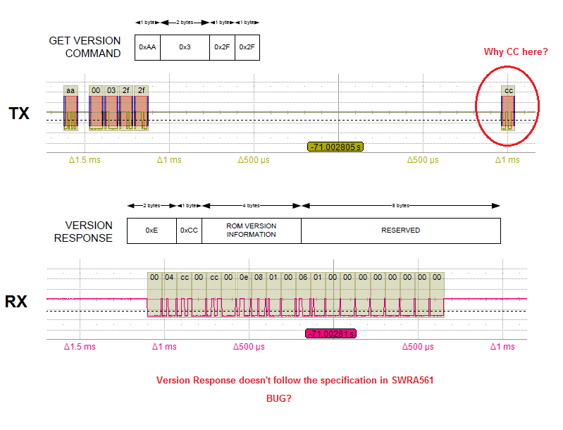
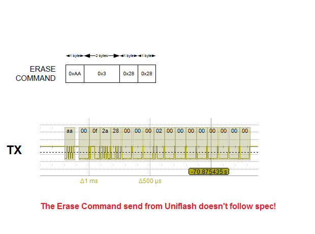
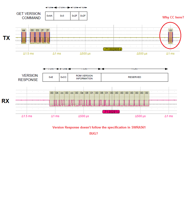
For the implementation in the host processor we need details about the UART protocol that the bootloader uses. I have found an application report "SWRA561", but there are some details (quite a lot actually) missing.

1. How is the checksum (4th byte) calculated in the commands (page 12 in SWRA561)?

2. Should the image according to the format in Chapter 2.1 be sent to the bootloader?

3. Should you use the "Image Creator" tool to create the image?

4. How is the image split into "WRITE TO FLASH" messages?

5. What byte order should be used when transfering the words in the image?


6. Are there any timing requirements you need to know about?

7. How do you interpret the STATUS word in "STATUS RESPONSE"

Are these other protocol details documented somewhere?

//Haakan

  • Hello,

    You are correct that some of the information required to implement flashing the mmWave board from a host processor does not seem to be present in the Bootloader app note. It will need to be added in a future version of the document.

    Here are responses for the first four questions.

    1. How is the checksum (4th byte) calculated in the commands (page 12 in SWRA561)?
    [TI] The 8-bit checksum in each UART command is a simple unsigned sum of the unsigned values of all the bytes of the payload of the command, where only the least-significant 8 bits of the sum are kept. For example, the pseudo-code to calculate the checksum could be:

    checksum = 0
    for each byte in the payload,
    checksum = (checksum + (unsigned) byte) AND 0xFF

    2. Should the image according to the format in Chapter 2.1 be sent to the bootloader?
    [TI] Yes, it should be sent using the sequence shown in "Figure 11. Flashing Sequence" in the app note.

    3. Should you use the "Image Creator" tool to create the image?
    [TI] Yes, the Image Creator tool should be used to create the MSS image. please see section "6. 5. xWR1xxx Image Creator" in the mmWave SDK user guide for more information. (The BSS image is already provided by TI in the mmWave SDK.)

    4. How is the image split into "WRITE TO FLASH" messages?
    [TI] The host processor needs to split the image into chunks and send each chunk in a UART "WRITE TO FLASH COMMAND". The "LENGTH" field of the command should be set to payload size (which includes the image data chunk and 1 byte for the 0x24 opcode) + 2. I am currently verifying the maximum chunk size.

    I am currently researching the last three questions and should have answers in another one to two days.

    Regards,
    John
  • Thanks John

    I have done some reverse engineering on the communication between UniFlash and IWR1443 and it seems like the communication doesn’t really follow the flow and protocol according to SWRA561.


    The flow seems to be as follows:


    UART Break

    Get Version Command

    Get Status Command

    Erase Command


    --- WRITE BSS SW ---

    Open Command

    Get Status Command

    Write To Flash Command

    .

    .

    .

    Write To Flash Command

    Get Status Command

    Close Command


    --- WRITE MSS SW ---

    Open Command

    Get Status Command

    Write To Flash Command

    .

    .

    .

    Write To Flash Command

    Get Status Command

    Close Command


    --- WRITE CONFIG (MEM_SWAP) ---

    Open Command

    Get Status Command

    Write To Flash Command

    .

    .

    .

    Write To Flash Command

    Get Status Command

    Close Command


    The commands/responses for Get Status and Erase seems to differ from the specification.


    Best Regards

    Haakan

  • Haakan,

    Thanks for the amount of detail in each question. I am working with the design team to find the reasons for the discrepancies between the app note and Uniflash and will reply once I have confirmed the answers (will most likely be tomorrow).

    Thanks,
    John
  • Haakan,

    Here are the responses for the remaining questions. I added question numbers for questions 8, 9, 10.


    Regarding question 4, the max image chunk size is 256 - 3 = 253 bytes. Uniflash is a bit more conservative and uses a max image chunk size of 240 bytes.

    5. What byte order should be used when transfering the words in the image?
    [TI] The byte order for the words in the UART commands is big-endian (i.e. transmit most-significant byte first). The BSS/MSS images should be transmitted as bytes in the order they are in the binary files.

    6. Are there any timing requirements you need to know about?
    [TI] The bootloader uses a command-response protocol. So the host should wait after sending each command until an ACK response is received from the device. Also, a few milliseconds delay is required between the OPEN command and write to SFLASH command as the bootloader erases the sectors corresponding to the FILE SIZE in the OPEN command.

    7. How do you interpret the STATUS word in "STATUS RESPONSE"
    [TI] The STATUS RESPONSE returned from the device is the bootloader error status based on the last command executed. The STATUS value returned is actually not used by the Uniflash right now. This is more to check if device is responsive. The possible returned STATUS values are as follows.
    0x40 = SUCCESS
    0x4B = ACCESS_IN_PROGRESS

    8. Observed VERSION RESPONSE does not match the app note.
    [TI] In Figure 10 in the app note, the VERSION RESPONSE row has an incorrect checksum column. It should say “CHECKSUM”, not “0xCC”. Also, Uniflash is sending a single-byte ACK (0xCC) to messages from the device, however this is not required and is actually ignored by the bootloader.

    9. Observed ERASE command does not match the app note.
    [TI] Uniflash supports additional storage type and size fields for erasing the flash. However, the bootloader doesn’t interpret these fields and just erases the entire SFLASH. The host could implement as shown in the app note.

    10. Overall flashing sequence used by Uniflash differs from Figure 11 in the app note.
    [TI] The ERASE command is not required but can be used to make sure the entire SDFLASH is cleared before the new images are written. The GET STATUS command is not required but can be used to check status of device. The GET VERSION command not required but can be used by the host processor to allow it to operate differently depending on the device silicon version (ES1/2/3).


    Additional note: The config image used to perform the memory swap from ROM to RAM after sending the BSS and MSS images can be found in the DFP package (www.ti.com/.../mmwave-dfp) at the following path after installing the DFP package: C:\ti\mmwave_dfp_01_00_00_01\firmware\masterss\xwr12xx_memswap.bin.

    Please mark the thread as answered if the questions are resolved or reply if more support is required.

    Regards,
    John
  • John,

    Thanks a lot!

    I have just one follow up comment on item 8. The response according to my image has more discrepancies compared to the app report than the checksum. For example the response length (first two bytes) is 0x4 and should b 0xE. The actual response length is obviously longer than 4 bytes. To me it seems like the VERSION RESPONSE has been partly overwritten by an ACK RESPONSE, i.e the beginning of the response is an ACK RESPONSE and the end is the VERSION RESPONSE. Can you please check if this is a bug in the bootloader. 

    Will there be any changes to the bootloader, in ES3, that affects the reprogramming commands/responses?

    BR

    Haakan

  • Haakan,

    The bootloader acknowledges the GET VERSION command by sending an ACK message to the host before sending the VERSION RESPONSE.

    For IWR1443 ES3, the low-level bootloader UART command protocol will be the same. However, the Image Creator tool will be used to produce a single combined image (similar to IWR1642) which will then be loaded during the flashing procedure rather than the three images (BSS, MSS, Config) that are uploaded currently.

    Regards,
    John
  • You are correct, the reponse to the GET VERSION COMMAND seems to be first a ACK RESPONSE and then the normal VERSION RESPONSE. Strange that some reponses have a ACK before the actual reponse. Not what I expected...

    Thanks for your help!