This thread has been locked.

If you have a related question, please click the "Ask a related question" button in the top right corner. The newly created question will be automatically linked to this question.

IWR1642: Antenna pattern on IWR1642EVM

Part Number: IWR1642

Hi TEAM,

I had got an antenna pattern question from customer. My customer copy IWR1642BOOST EVM antenna in HFSS software, all the size and the parameter are same with IWR1642BOOST EVM, but he can't get the same pattern as EVM did.

Could you please help to point out which parameter will cause this pattern? Is the RF source should began from BGA ball and transmit line?
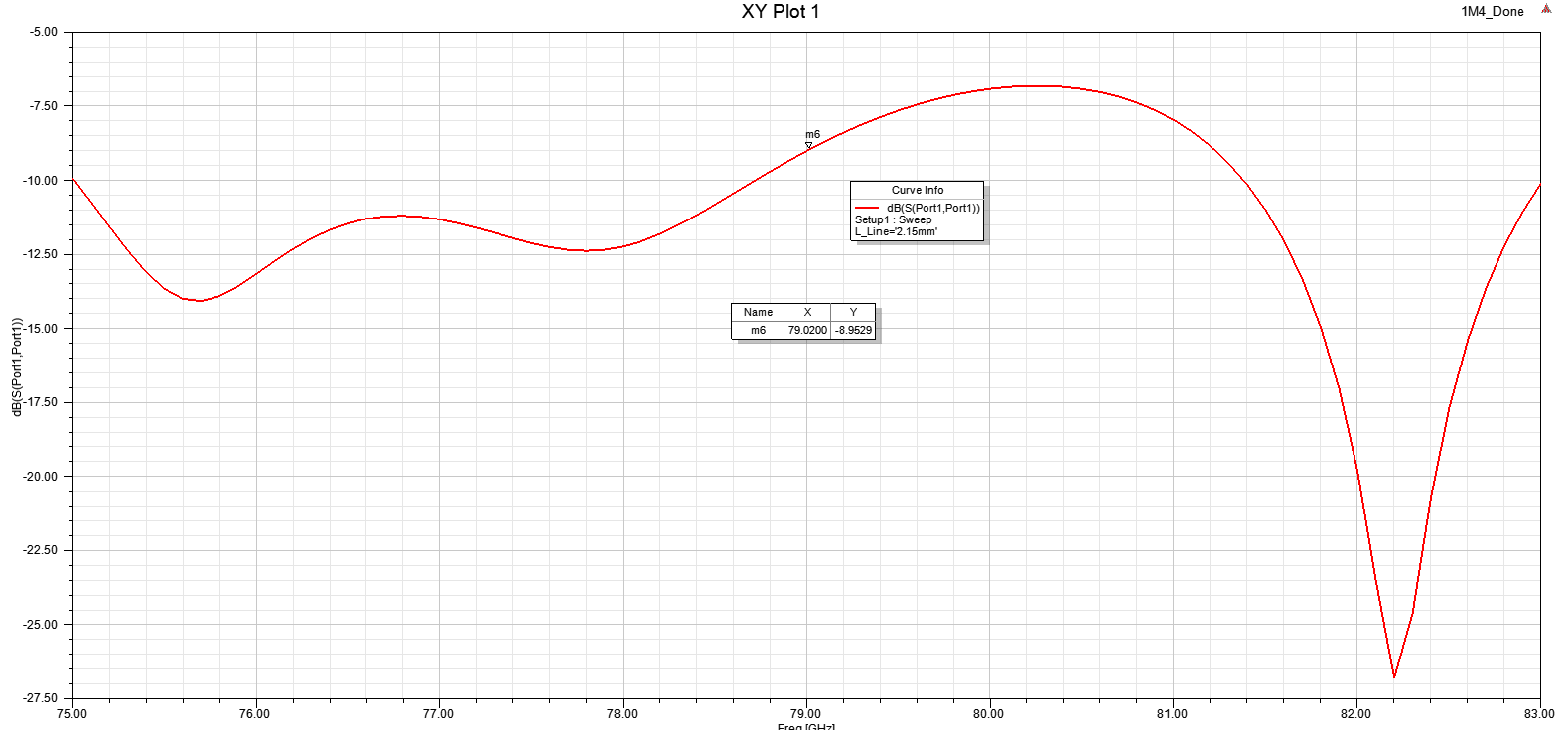
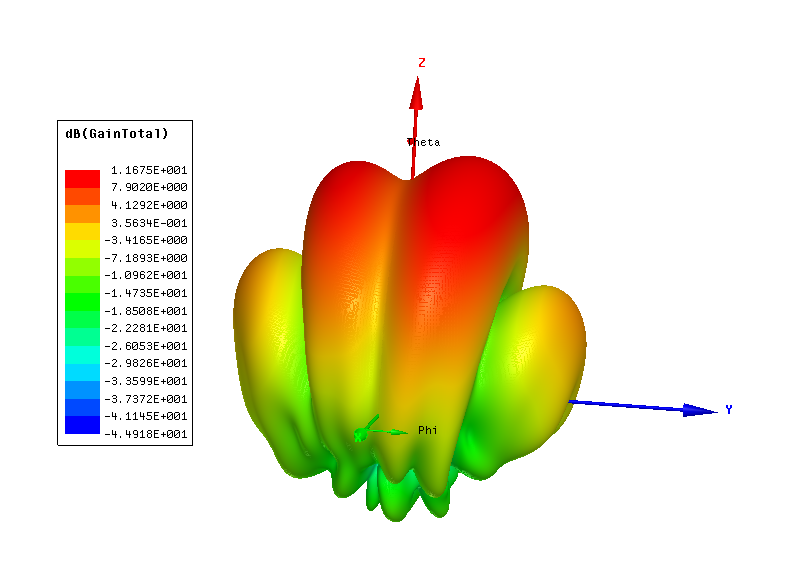
Antenna pattern and the S11 figure are attached below.
Thanks.

Regards,
Wesley

  • Hello,

    You need to use the EVM stackup.
    Please refer to the below app-note for the stack up and transition dimension and guidelines.
    www.ti.com/.../spracg5.pdf
  • Hi Chethan,

    Thanks for your reply.

    Customer is curious about the RF source port. Should the simulation RF source port begin from BGA ball? Or the simulation can only start from the end of GCPW line?

    Regards,

    Wesley

  • Wesley,

    To get an optimal match between the device RF ball and PCB trace, the package to PCB transition layout
    needs to be designed appropriately. TI has built Rogers-based EVM boards and recommends the
    customer who uses Rogers materials, to use TI’s recommended transition. This transition allows the
    package to match to a 50 Ω transmission line at the edge of the package (approximately 1.3 mm from the
    center of the signal pad, This is the reference plane for the 50 Ohm).
    If the customer chooses to use a different PCB substrate, the package to PCB transition needs to be re-designed.

    Typically RF source point is kept at the feeding point close to Antenna and optimize the Antenna geometry/ stack-up to get the desirable radiation pattern and field of view. And then you attach the transmission line to the Antenna feed all the way to the device. If the transmission lines (in this case GCPW) are designed correctly then, radiation pattern should not change too much w.r.t. original Antenna element's simulation. In reality there would be slight degradation to the extent mismatch.

    Thanks and regards,
    CHETHAN KUMAR Y.B.
  • Got it. Thanks for your great support.