


Sir/Mdam,
We are using LDC1312 in one of automotive sensor.
The brief application is as below
The LDC 1312 measures the linear distance -2mm to +2mm of target metal movement. The LDC1312 is interfaced to micro controller. Micro controller converts the measured distance into PWM which in turn converted to analog output using RC and Opamp.
This system is working OK at ambient of 25 deg C.But output is drifted by almost 1.2V at temperature approximately 75 to 80 deg C.
The coil Gerber is attached for your reference.
The coil PCB is
|
PCB MATERIAL |
FR4 |
|
PCB THICKNESS |
0.8 mm |
|
NO. OF. LAYER |
2 |
|
PCB SIZE |
21.4mmX 14.5 mm |
|
HAL |
Tin-Lead |
|
COPPER LAYER IN MICRONS |
35 micron (FINAL) |
|
MASKING |
GREEN MASK |
|
LEGEND PRINTING |
WHITE |
|
NO.OF PCB REQUIRED |
100 |
|
Gerber & NC Drill file name |
GERBER for BIN-coil-REV2 |
I
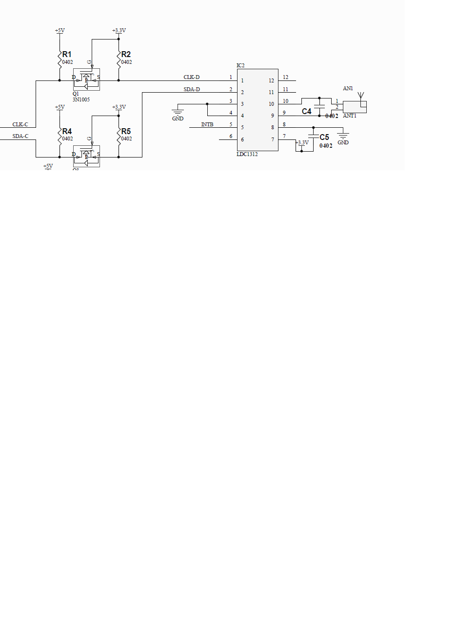
The LDC scheme is

