This thread has been locked.

If you have a related question, please click the "Ask a related question" button in the top right corner. The newly created question will be automatically linked to this question.

PGA450Q1EVM: GUI EEPROM not reading EEPROM

Part Number: PGA450Q1EVM
Other Parts Discussed in Thread: PGA450-Q1, TIDA-00151

Hi,

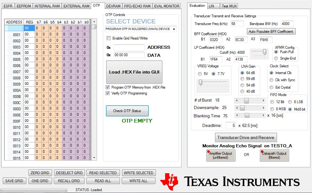
I am using our one PGA450 board.We tested with 10 boards and working fine(OTP memory).Suddenly OTP programming not working.

The write operation of Threshold value success.But when i read, the GUI shows '0' instead of data.

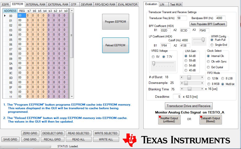
My GUI not able to read EEPROM data from PGA450.It shows 0 only.

DEVRAM programming working fine without verification.

  • Hi Arun,

    Can you list your procedure of programming the OTP and EEPROM?
    Whenever you are reading or writing to the EEPROM, is the MICRO is the RESET state?
    For the OTP programming, is your VPROG_OTP at 8V during the time of programming?
    Keep in mind that if a device is programmed to DEVRAM, you cannot revert it to OTP mode, and vice-versa.

    Your procedure should match the following for programming the OTP and EEPROM:

    While the microcontroller is active, the MICRO RESET test register is the only register accessible through SPI. The device must be put into the RESET state before sending additional SPI commands, including the OTP and EEPROM SPI programming commands. To put the microcontroller in reset, write a 1 to bit 0 of the MICRO RESET (address 0x2F) test register. Transmit the TEST Write SPI command in the following order: 0x16, 0x2F, 0x01.

    Prior to starting the OTP programming process, raising the VPROG_OTP pin on the PGA450-Q1 to 8 V is required. When the voltage on this device pin reaches this level, the OTP programming mode is enabled. The OTP programming voltage should not be connected to the pin for an extended period of time. Do not power up OR power down the PGA450-Q1 with the VPROG_OTP pin set to 8 V, this may cause unrecoverable corruption to the OTP data.

    The following is the OTP memory programming procedure:
    1. After power up, set the VPROG_OTP pin to 8 V.
    2. Send an OTP write command through the SPI.
    3. The CS pin is set to HIGH at least 100 μs for the OTP programming process to complete. Do not perform any SPI write operations to the OTP during the OTP programming process.
    4. Repeat Steps 2 and 3 until all desired OTP addresses have been programmed.
    5. Before powering down the PGA450-Q1 device, disconnect the 8-V supply to VPROG_OTP pin.

    The following is the EEPROM memory programming procedure:
    1. Write data to EEPROM cache – Use the 8051W MOVX assembly instruction to place data in external memory addresses 0x0400 through 0x041F.
    2. Write a 1 to the WRITE bit in the EE_CTRL register.
    3. Continuously poll the EE_STATUS bit in EE_CTRL register for the programming status. The EEPROM programming requires 70 ms to complete.

    To bring the microcontroller out of reset after programming the OTP and EEPROM, write a 0 to bit 0 of the MICRO RESET (address 0x2F) test register. Transmit the TEST Write SPI command in the following order: 0x16, 0x2F, 0x00.
  • Hi Akeem,

    I am using TI-GER board for programming the PGA450-Q1. As per mentioned procedure followed for programming.

    VPROG_OTP on this PGA450 measured 8.2V

    The EVM board itself not showing burst / Echo.But data coming from PGA450 SPI port when i see in the oscilloscope.

    After programming OTP its again shows OTP Empty.

    Attached image for your reference.

  • Hi Arun,

    What are the values of the following test points during the OTP programming sequence, and do any of these power rails droop or fail low during OTP programming?:
    VPWR, DVDD, AVDD, VPROG_OTP, SDO, SDI, SCLK, CS'

    Please confirm the following:
    1) When the MICRO is placed in the RESET state, can you perform an ESFR register read of address 0xB4 (TEMP_SENS). If the SPI is connected properly, and the device is receiving sufficient power at VPWR, this value will always return a non-zero value.

    2) The PGA450 device you are attempting to OTP program has not been previously OTP programmed. See the following post for instructions on checking the OTP memory before programming: e2e.ti.com/.../2677765

    3) The SPI bus is properly bridged from the TIGER board to your custom PGA450 hardware. See the following discussion for a diagram for socketed programming example: e2e.ti.com/.../728793

    4) The hardware you are attempting to program is not the PGA450Q1EVM-S (TIDA-00151) hardware purchasable from the TI eStore. This unit is already OTP programmed to run from OTP memory.

    5) The process you are using now previously worked for the other 10 units you mentioned. Is there anything different about the hardware or software setup of this unit you are debugging?
  • Hi Akem,

    There is no drop on VPWR, DVDD, AVDD, VPROG_OTP, SDO, SDI, SCLK, CS pin during OTP programming.

    1.TEMP_SENS value shows zero value.

    2. OTP programming is working with another new PCB assembly.(May be the existing device memory wrongly programmed)

     3.The SPI bus is properly bridged from the TIGER board as per the PGA450 hardware.We are using IO-CS pin for our custom board communication.(Deselected the verification box during programming)

    4.We are using our customized hardware and PCB for testing. PGA450Q1-EVM is only used initial study and sensor tuning.

    5.The PCB hardware and software are same as previous tested one.

    Kindly resolve my issue regarding the data reading from PGA450 to GUI.(When i tried with GUI manual GER board SPI operation, all SPI pins are changing the state when corresponding button pressed on the GUI except MISO pin. MISO pin always in high impedance state.) 

  • Hi Arun,

    If the this PGA450-Q1 unit is not responsive to any SPI commands, it may be damaged. Given that it does not return a non-zero value when reading the TEMP_SENS value through SPI in the RESET state, I suspect the other other commands or programming methods will also be ignored. We first need to understand why SPI communication is failing.

    What is the PGA450-Q1 current to VPWR when supplying voltage to the device? The quiet mode current should be 5~7.5mA when first powered on and idle. If the device shows 5~7.5mA of current, then check the levels of AVDD and DVDD, which should be 5V and 1.8V respectively. If all these levels are good, then the SPI block should be active. Note that the

    Have you done a waveform comparison of a good unit versus this bad unit to check if there are any differences on the MOSI, MISO, SCLK, or CS pins?