This thread has been locked.

If you have a related question, please click the "Ask a related question" button in the top right corner. The newly created question will be automatically linked to this question.

AWR1642: ADC output values

Part Number: AWR1642

HI: 

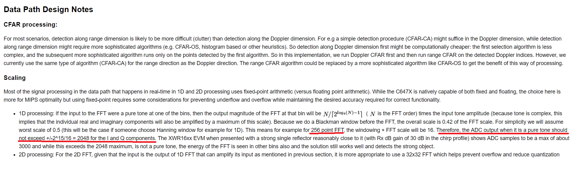
My question is about ADC out of AWR1642. Shown as follows, the doxygen indicates that the value of ADC outputs will not exceed +/-2048 to avoid overflow/nuderflow in 1D FFT (size of 256) outputs.
My questions:

  1. if the size of FFT is changed, is the full scale (FS) of ADC output also changed? 
  2. Does the limitation of FS of ADC be mentioned in other document?  I don't find the similar content in the datasheet and other training documents.
  3. what is the input range of ADC of AWR1642? I also don't find in the datasheet.

Thx

Stan 

  • Stan,

    Please find answers below

    if the size of FFT is changed, is the full scale (FS) of ADC output also changed?
    No. Full scale of ADC data is not changed, it would depend on ADC Out configuration

    Does the limitation of FS of ADC be mentioned in other document? I don't find the similar content in the datasheet and other training documents.
    Which Limitation. Can you check ADC configuration API. You can configure FS of ADC to 12,14,16 bit values.

    what is the input range of ADC of AWR1642? I also don't find in the datasheet.
    Can you check ADC configuration API. You can configure FS of ADC to 12,14,16 bit values.

    API document
    C:\ti\mmwave_sdk_<ver>\packages\ti\control\mmwavelink\docs\doxygen\html

    C:/ti/mmwave_sdk__<ver>/packages/ti/control/mmwavelink/docs/doxygen/html/structrl_adc_bit_format__t.html


    Regards,
    Kaushal
  • Dear Kaushal:

    Thanks for replay.

    I have read your replay and checked the ADC bit values. However, I am still confused.
    Let N be the ADC bit value. Do you mean that the FS of ADC = +/- 2^(N-1)?
    If yes, why does the doxygen indicate that the max value of ADC output does not exceed 2048 if N = 16 (please refer to the part highlighted in red)?
    If not, what true value is the FS for N = 16?
    Could you give a more detailed explanation?

    Also, I would like to know what voltage each adc output codeword represents. For example, what voltage does the codeword 0x0000 stand for if N = 16? Could you help me? Thx.

    Regards,
    Stan
  • Your questions seem to have originated from a misunderstanding of the text you quoted, perhaps it is because of how we have expressed the information may be causing confusion. What we are doing here is working backwards if we had for example a 256-point FFT (implying the profile had <= 256 adc samples), what "should be" (as opposed to what "will be")  the ADC output max so that the fixed point FFT calculation does not result in overflow. It is not that somehow the ADC hardware itself is scaling based on number of ADC samples or the FFT order (the next power of 2 of ADC samples) i.e we are working backwards and checking if we need any scaling such as with adjustment of Rx gain in the profile or another way would be to scale digitally in the data path processing.

    In the said experiment it seems there isn't a concern with the Rx gain setting of 30 dB. The purpose here is to make user aware of this issue that there is a possibility of overflow depending on their application and there may be artifacts that may require one to scale down and the information in the doxygen gives some guidance about this. Even when you place a corner reflector near the sensor, all energy is not going to get concentrated in a single FFT bin due to the presence of noise and real-world environments are not anechoic chambers (our measurement wasn't in an anechoic chamber, it was in an office environment). So the theoretical calculation of what max ADC samples would be for a pure tone is an idealization and hence even when we see higher than the max, we don't necessarily see any artifacts and hence we declared that we are o.k.

    The calculation may make one think that for an FFT size of say 1024, there may be a problem because the ADC output needs to be even lower as per the calculation to not cause overflow, but we have checked this also and we didn't notice anything unusual in the same experimental conditions. This is because there is an HPF in the front-end (this is documented in the device documents and elaborated/explained in various forum posts) which will attenuate close reflections and with a higher number of adc samples, typically the slope being lower for this case (due to max sampling rate limit) will increasing the max distance that HPF will take effect and this in turn will lower the incoming max signal power (R^2 loss in each direction, effectively an R^4 scale) i.e you will have to move the corner reflector farther than with bigger slope (and therefore smaller number of adc samples and hence smaller FFT) so while a FFT of 1024 will require a large (down-)scaling of ADC samples to prevent overflow, the incoming (max for close object) RF will be smaller than the 256 FFT case and so there is a balancing out here.

    In summary, you should do a check for your application requirements if you see any artifacts after 1D processing that may be because of FFT calculation overflow and if necessary either change the Rx gain setting or introduce digital scaling in the processing chain before doing FFT.

  • Your reply really helps me.

    thanks, Piyush.