This thread has been locked.

If you have a related question, please click the "Ask a related question" button in the top right corner. The newly created question will be automatically linked to this question.

OPT9221: Reference of test patterns are missing in the documentation.

Part Number: OPT9221

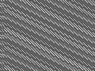
I am taking a new prototype into operation. The OPT9221 delivers datat directly into an FPGA which is supposed to do something with the depth data but currently is configured to just forward the meta pixels (32Bit). I am getting depth images in 4-Byte-mode (DE0x25 OP_DATA_ARRANGE_MODE = 0). Since I am having issues with the depth data I first have to rule out the FPGA part is not doing any unintended byte manipulations. Thus, I have activated ROW-ramp test-pattern (DE0x31 MAC_TEST_ENABLE = 1, RAMP_PAT = 1) and optained this test image for amplitude data:

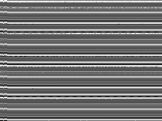
Next I activate the column test pattern Thus, I have activated ROW-ramp test-pattern (DE0x31 MAC_TEST_ENABLE = 1, RAMP_PAT = 2) and optain this image for amplitude data:

Both images are obviously ill formed. 

Now I would need the reference images how the data should look like in these modes (that is, what test patterns are for). But these references cannot be found in the SBAS703A –JUNE 2015–REVISED JUNE 2015 OPT9221 chip documentation. Could you plese provide the expected test data images. This would help a lot.

I assume the continous pixel data is comming out the chip in a little-endian format: AC0-Byte0, AC0-Byte1, FP0-Byte2, FP0-Byte3, AC1-Byte0, AC1-Byte1, FP1-Byte2, FP1-Byte3 ...

Hopefully this assumption is right?

Thanks in advance, Frank.

  • Frank,

    For the MAC_TEST data not to change with time:
    1) Please ensure that DELAY_FB_CORR_MODE and DELAY_FB_DC_CORR_MODE registers are set to 0.
    2) Please ensure that temperature compensation is disabled (COEFF_ILLUM = 0, COEFF_SENSOR = 0).

    The images shown do not look a lot different from the expected values. You can check the example VXL files for MAC_TEST here:
    github.com/.../opt8241-example-data. You can parse binaries using Voxel Viewer software (www.ti.com/.../sbac143)

    Note that these may differ slightly, based on register settings, but you can compare the same.

    Suramya
  • Suramya,

    I have Firmware 0.31 installed on the sensor. Is there any update I shoul use?

    before starting the capture of test images I checkted the register settings you mentioned above. They carry their default values:

    PID:03440057 TID:03450056 OM/TOF(I): OPT9221DE_REG_FB_CONTROL: 0x005604
    PID:03440057 TID:03450056 OM/TOF(I): OPT9221DE_REG_COEFF_ILLUM: 0x000000
    PID:03440057 TID:03450056 OM/TOF(I): OPT9221DE_REG_COEFF_SENSOR: 0x000000

    The noise on the test images stays the same. Are there any other register settings that may influence the quality of the test images obtained? Meanwhile I have also checked the FRAME_RAMP mode but it shows the same noise:

    Also, can you please confirm the sequence of bytes obtained when operating in 4-Byte mode? It is about the endianess. Each meta-pixel has four bytes. First amplitude then phase is transmitted. For the amplitude is Byte-0 transmitted first or Byte-1? It is not clear from the OPT9221 documentation.

  • Hi Frank, 

    Data is returned as little-endian. Based on the patterns, your decoding is correct. 

    By noise, do you mean the pattern on the left edge of the image? That is expected. If you see the example data, you'll see a similar pattern. The frame ramp pattern looks similar to the one we get from the OPT8241-CDK-EVM. 

    For verifying the test pattern, it would be best if you captured the pattern when the camera is running properly (reference pattern) and compare the received test pattern to the reference pattern for checking if OPT9221 is working correctly. The actual pattern on the left edge shouldn't matter for the same. 

    Suramya

  • Hello Suramya,

    meanwhile we performed much more testing and we have found a severe problem with our implementation. Here are steps that we have performed:

    1. I suspected that there could still be a problem with the parallel data interface. Hence, I activated the PHY_TEST in DE:R0x29 (Bit1). And then I discovered that we were having problems with the sampling of the OP9221 OP_DATA bits.
    2. The team I work with attached probes to the OP_PIXCLK (green) and OP_DATA bits 0 (cyan) and 1 (magenta) which were suspected to have sampling problems. We observed the following waveforms:

      This was especally disturbing since in the OPT9221 documentation clearly says the opposite. This  is drawn on page 13:

      Even more confusing, on page 25 one finds a diagram that suggests the the data must actually be sampled on the falling edge of OP_CLK!

      We first tried to negate the clock polarity with respect to the data by setting Bit5 in DE:R0x39 (OP_CLK_EDGE). This had no effect on the observed OP_PIXCLK!
      When we saw the Osciloscopes output did not change while programming DE:0x39, we changed the FPGA-design to sample the data on the falling edge of the OP_CLK signal. This did help and we optained decent test data with the PHY_TEST bit still active.
    3. Now I deactivated the PHY_TEST and came back to the MAC_TEST again. As an example here is the phase image I am getting from the TFC now:

      The image is a 8Bit gray image containing the 8MSBs out of the 12Bits the sensor has to offer.
    4. I asked myself were these stripes (one pixel wide) are comming from. They all carry the same gray value of 0xB8. After further debugging I found out that at exactly these pixels the auxiliary depth data is indicating pixel saturation

    My question now is: Are the saturation pixels part of the intended test data the OPT9221 is supposed to output? - since I am using FW0.31 this could have changed. I mean the test data could have been enriched.

    I wonder because pixel saturation is not seen in the VoxelViewer-test-data that I could download from the official VoxelSDK GitHub site.

    I also would like to raise the request to update the information in the OPT9221 data sheet:

    1. The information on page 13 seems to be clearly wrong. Data has to be sampled on the falling edge of OP_CLK.
    2. Please add the expected test images to the documentation (MAC_TEST - phase and amplitude), (PHY_TEST) as this would help a lot in comparing what one is getting and what one is supposed to get. In addition a pointer to the GitHub page would be appreciated in the documentation as well.
    3. Bit5 of DE:R0x39 does seem to have no effect. Is this a firmware bug?

    Best Regards,

    Frank.

  • Hello Suramya,

    Can you confirm that the diagram in Fig.1 on page 13 of the OPT9221 documentation is wrong and that the OP_DATA* lines must be sampled at the falling edge of the OP_PIXCLK?

    Regards,

    Frank.

  • Hi Frank,

    Sorry for the late response.
    Yes, the data needs to be sampled on the falling edge of OP_CLK.

    We'll be updating the datasheet with corrections and mac_test_en and ply_test patterns in the next revision.
    Suramya