This thread has been locked.

If you have a related question, please click the "Ask a related question" button in the top right corner. The newly created question will be automatically linked to this question.

TDC1000: TDC concentration measurement metal tank 2mm steel.

Part Number: TDC1000
Other Parts Discussed in Thread: TDC7200

Metal cylinder measurement using tdc1000. I  have a custom board using a pic microcontroller and everything works fine when used with thin metals and plastic 

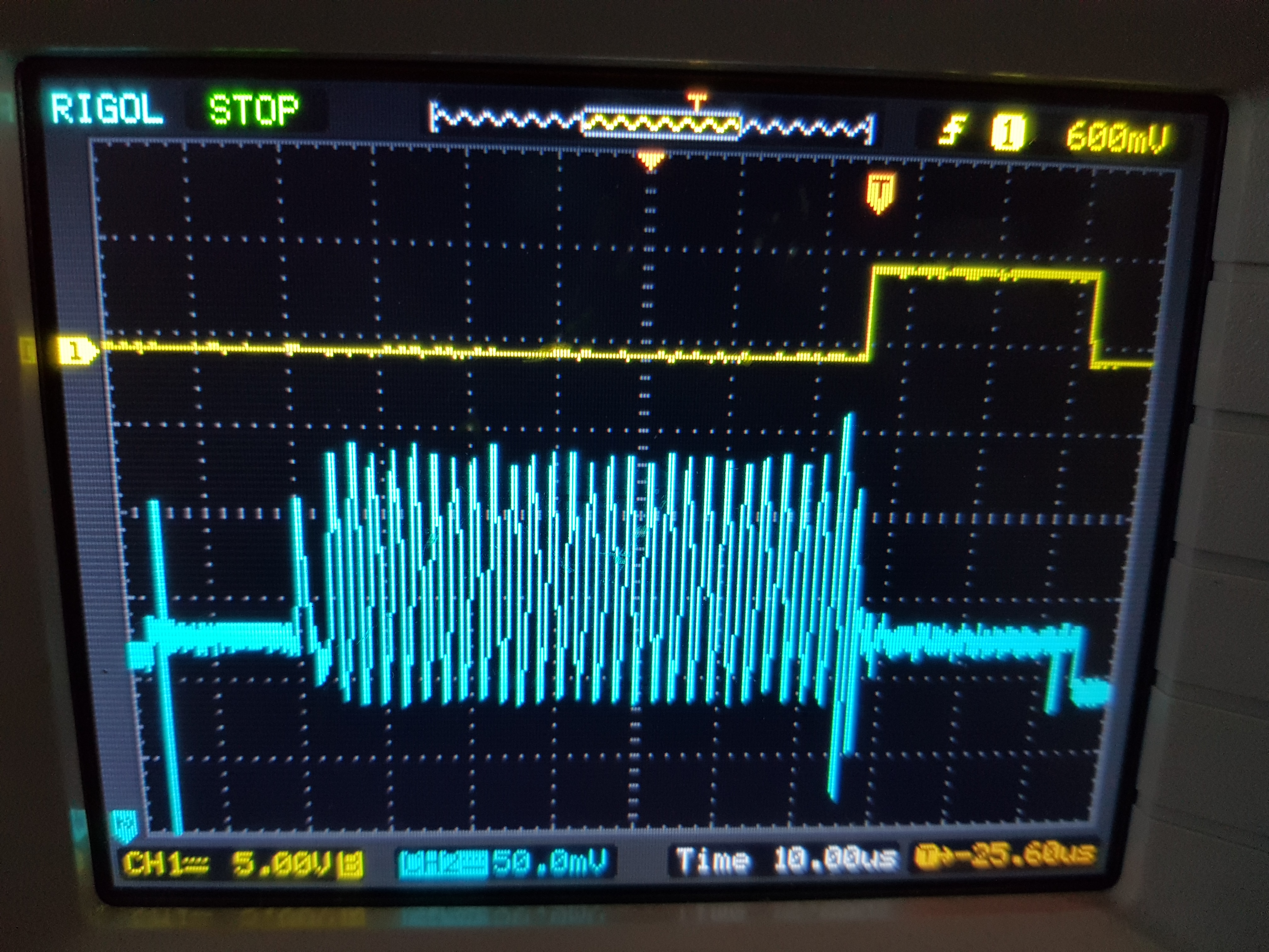
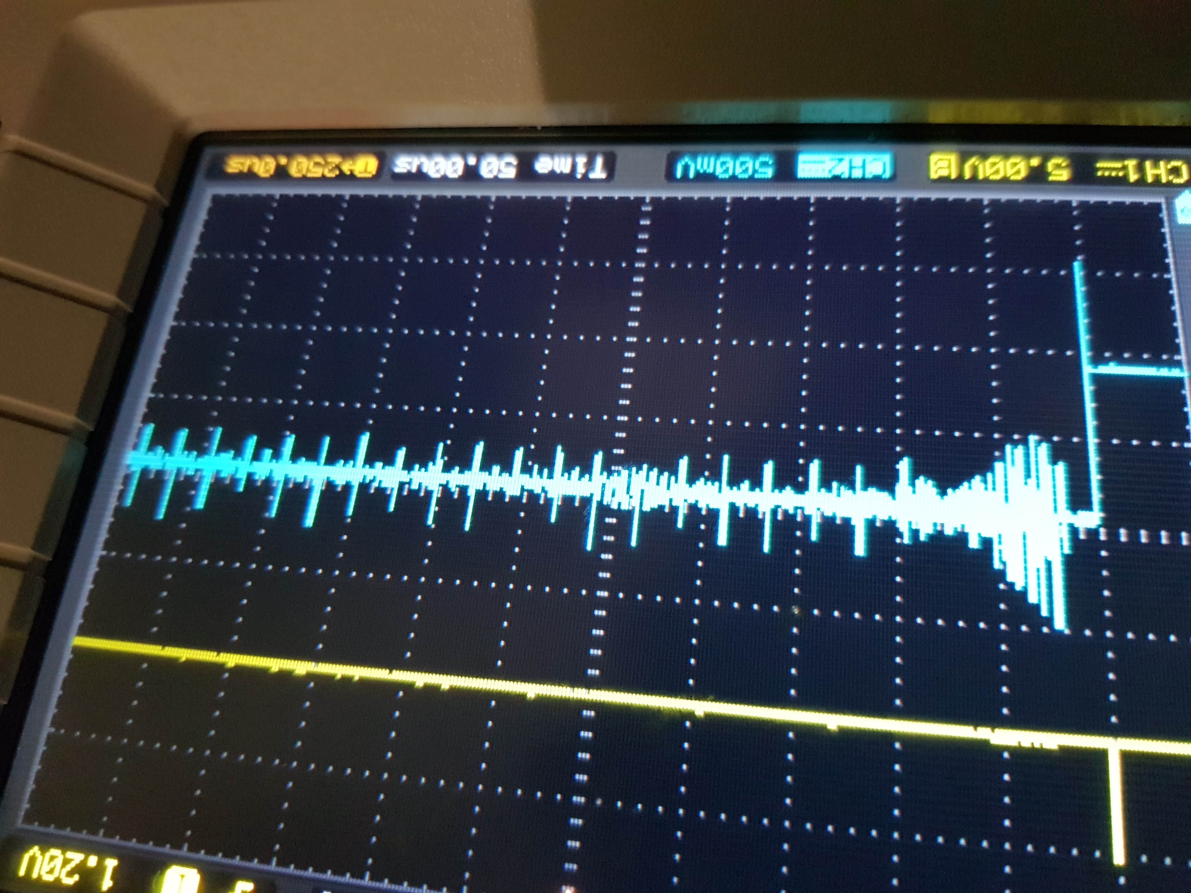
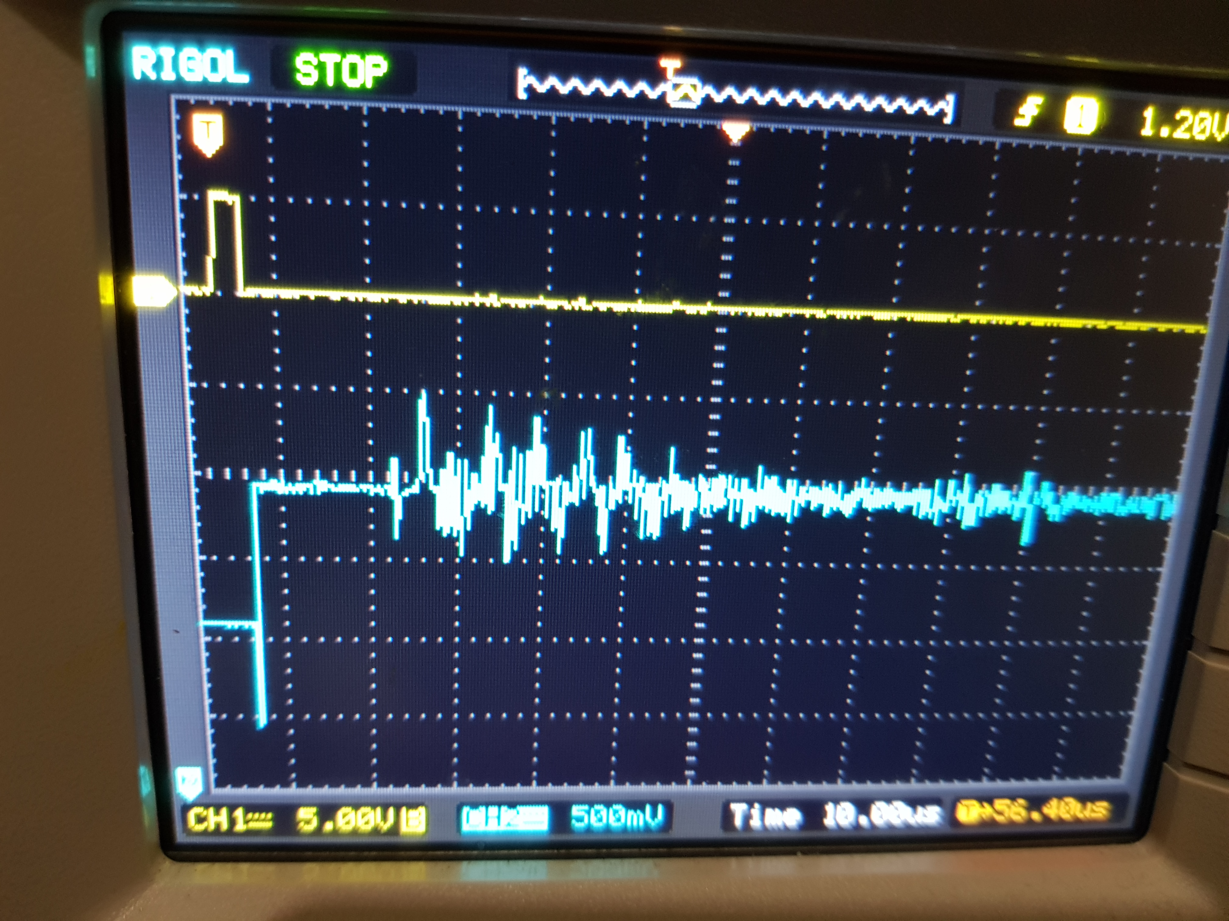
enclosures. However when i use a metal cylinder  2mm thick the waveform I am seeing looks unusual. When measuring concentration should the receive mode be single echo?

The diameter of the cylinder is 0.30 meters and the microcontroller is reporting 4000 ticks at 100ns. The liquid is lpg.  I have used the techniques provided to mount the sensor which is a stemic 1mhz 15mm. What your seeing is the stop pulse and the signal on the compin pin.

thld - 125mv

gain 21db

autozero 64us

tx pulses = 1

rx pulses = 1

  • Fernando,

    Your waveform looks normal, please let me know if you do get the TOF.
  • Can you provide more insight. There is a huge spike after the tx pulse then there is a pause followed by wave with almost the same amplitude. Is that ring down? Then there is a massive spike. Can I assume that is the echo.
  • Time is too short. What is the relationship between frequency and the ability to penetrate a medium? Since I have switched to metal i have been getting unpredictable results. What is Q of the transducer and how can it help? Can I also have a proper explanation of autozero?

  • CAN SOMEONE WHO HAS KNOWLEDGE OF THIS PRODUCT PROVIDE A RESPONSE? THIS IS VERY FRUSTRATING..
  • The signal post that spike is an ring down effect & the rest before that should be your echo.
    Typically in thicker container you could have 2 separate echo one from the boundary of the metal/container & the other from the actual reflection of the LPG in this case. You will need to take TOF measurement from both to get the correct TOF. While measuring concentration you will know the actual TOF say on a standard liquid for the given distance of the container.
    Also higher the frequency higher is its ability to penetrate a medium.
    The vibrations of a transducer with a high “Q” are “dampened” or significantly reduced once the driving frequency changes very slightly from its resonant frequency. The low “Q” transducer continues to vibrate with a considerable portion of its maximum amplitude even if the driving frequency deviates moderately from the resonant frequency. The width of the frequency range that will cause vibration of a particular scale is called the “Q” of the transducer.
    Please refer the section "8.3.6 Comparators for STOP Pulse Generation" in TDC1000 Datasheet to understand the auto-zero.
  • I read the datasheet on autozero but was not clear. Based on experimentation it seems to try to reduce a signal over a specified time.

    I have gone back to basics and disabled rx pulses so that I can simply see the waveform.  I am generating 3 tx pules.  The diameter of the cylinder is 30cm. Can you make sense of this signal? I am seeing spikes repeating at 25us. Is ringdown enhanced when the sensor is connected to metal? I have invested tons of time in the hardware and software and it all works until it sees metal. What puzzles me is I have a commercial device  here with minimal parts run on a small 3.6 volt battery and has no issues with the same tank. What are we missing? I am using a 15mm sensor should it be smaller or bigger. There is an example of TI member taken measurements through a metal pot. What size sensor was used and what was the thickness of the material? When should the 30 boaster circuit be implemented? Is the boaster evm sold seperately?

     Can someone also properly explain the operation of the two fets responsible for shutting down the transducer driver? The driver IC and the receive path with the two diodes. Are the two diodes to clamp the signal? Why is OUTH connected to OUTL? 

    Any Help with this will be greatly appreciated.

  • Mr Bharat Sir you assistance is required. Someone must have intimate knowledge of the product being sold. This is the real world not university (Metal containers).
  • Fernando,

    As in the Fig. 20 in the datasheet of TDC1000, The STOP pulse generation block of the TDC1000 contains two auto-zeroed comparators (a zero-cross detect and a threshold-detect comparator), a threshold setting DAC, and an event manager. The DAC helps to bring the VCOM pin very close to the COMPIN pin there by reducing the offset between the COMPIN & VCOM. This event would require a certain time to settle & The duration of auto-zero period is configured with the AUTOZERO_PERIOD field located in the CLOCK_RATE register.

    I find that in your original screen shot of COMPIN pin & STOP, the COMPIN pin does seem to have some signal, however the COMPIN pin comes before the STOP signal, this could be due to blanking/mask. Please check if your STOP signal is arrive much later that you expect it to come up. You could be blanking the time period within which you are receiving the Rx signals.

    In general we would require large transducers to send/receive in ultrasonic signals through metals. I assume you are using TI TDC1000-GASEVM, while the TDC1000-BSTEVM comes with a booster circuit which can boost the signal up to 30V.

    The 2 FETs in the TDC1000-GASEVM is used to drive the transducers in the EVM, the EN pin is floating and that let the FETs in normal operation mode & when the IN is high the OUTL & OUTH are both High. Please refer to the table 2 on the FET datasheet: www.ti.com/.../ucc27537.pdf

    The 2 diodes D3 are connected to prevent any current from the transducers to go into the AVDD.
  •  Still not clear on autozero. Either i am dumb or your explanation is poor.   I prefer we focus on the last screen shots where the rx pulse are disable so the waveform can be observed. I am not able to make sense of the waveform.I am using a custom board.

    Also whats the point of connecting two high outputs together? I am just having lots of trouble with using and understanding your solutions. I never have this issue with Microchip.

    Just spent another 3 hours on this using the tdc1000-tdc7200 evm and changing all the possible parameters with no consistent result . I am thinking there is a flaw with this product and metals between

    2mm  to 4mm.  I await someone to prove me wrong.

  • Fernando,

    We do not have any data with a measuring flow/water level in a metal tank of 2mm thickness. Like i said before, i understand you do not receive any receive signal in the device. I would check the signal at the transducer when it sends the pulses & when it receives the return pulses. I suspect the transducer is not receiving the return signals as expected.
  • The beauty of ultrasound is being able to measure without seeing. I would have thought the limits of this application would have been tested.

    I have moved on to understanding the tdc7200 until my power board pcb is manufactured. I am using assembly on a byte device. When using a 8mhz clock will the TIME registers go over 16 bits?

    Also in Multi cylce readings the value in the count and time registers is n times the at the end of n cylces?
  • The 2 diodes D3 are connected to prevent any current from the transducers to go into the AVDD. ????????how.