This thread has been locked.

If you have a related question, please click the "Ask a related question" button in the top right corner. The newly created question will be automatically linked to this question.

LVDT not behaving as expected

Other Parts Discussed in Thread: TL082

Hello,

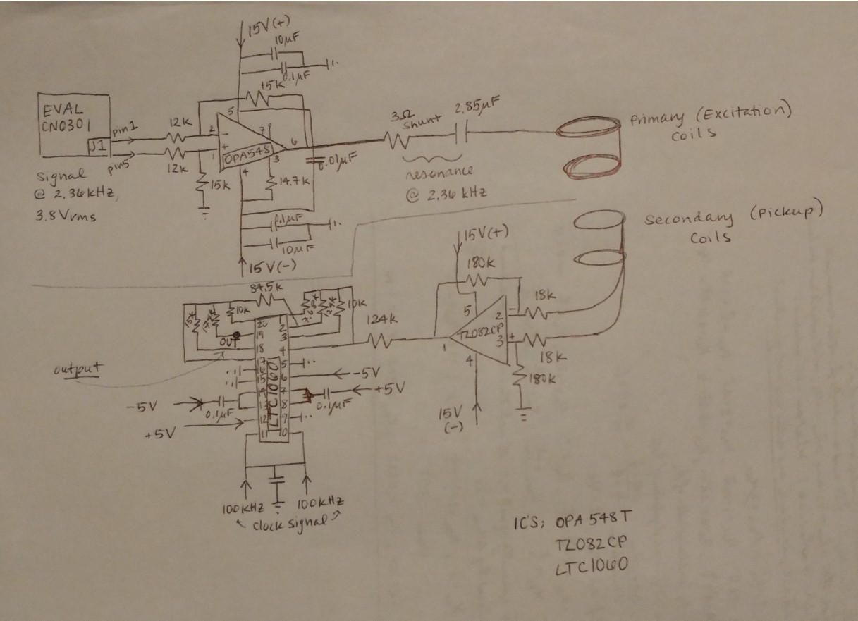
I have constructed an LVDT that is not behaving as it theoretically should.  I have eliminated so many possibilities for its malfunction that I thought I would post on here to see if anyone would help.  I have been running COMSOL simulations with altered coil numbers and geometrical asymmetries to see if I could reproduce the behavior with no success. 

I've wound a 3D printed form with excitation (primary) coils (30 turns) and pick up (secondary) coils (2 unconnected sets of 30 turns which add to 60 turns).  It's a large LVDT, the radius is .10008 m and the length is .09906 m.  I have 1.035 A running through it 

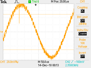
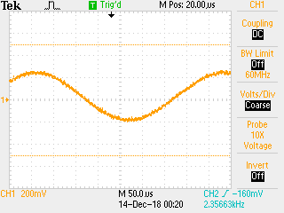
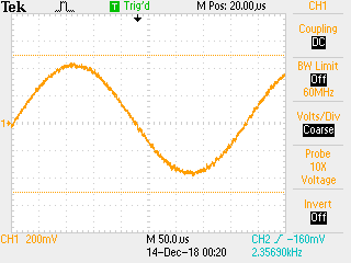
Here is what is happening: I have a 1 inch steel ball that I use as the core, as I move it from the right hand secondary coil to the left side coil, there is a huge response at the right hand secondary coil, then once the ball passes the null position the response doesn't change much except show a phase shift, the signal actually decreases a bit at the left coil.  The amplitude response seems to be concentrated on the right coil and the phase response concentrated on the left.  

Can anyone explain this strange behavior?  I'm a graduate student at NASA Langley and my advisor can't explain what's happening, nor can the electronics expert.

Any help or assistance would be very appreciated. 

Thank you,

Michelle

  • Hello Michelle,

      Would you please provide a schematic of the electrical components of this design?  Please include all power sources, electrical connections to the coils, etc.  Reading your description I'm not understanding what electronic circuitry is involved and specifically what ICs are in use.  Once we see the circuitry involved, we will better be able to assist.  

    Thank you!

    ~Leonard 


  • Hi Leonard, above is the schematic I drew including all the ICs, power supplies, inputs, and passive components.  Please let me know if I can elaborate on anything else.

    Thank you so much for taking the time to help.

    Michelle

  • Hi Michelle,

    I'm not an expert on LVDTs, but I'll try to help you out and see if the TL082 is working as desired.

    Can you provide some oscilloscope shots (or other empirical data) of the following:
    * Input signals for the TL082 when the ball is left, right, neutral (to compare against each other)
    * Output signals for the TL082 when the ball is left, right, neutral

    It would also be useful to see if the signal that is driving the primary coil stays the same as the ball is moved into the various positions.

    Thanks,
    Paul

  • Hi Paul,

    Thank you so much for offering your help.  I've attached all the signals from the scope that you requested.  The signal driving the primary coil does stay the same when I move the ball around, so at least that works!

    Please let me know what you think.

    Thanks again,

    Michelle

     in, left   in, neutral   in, right 

    out, left   out, neutral   out, right 

  • Hi Michelle,

    At least on a basic level, the op-amp appears to be doing it's job of amplifying the signals by 10 - the inputs under various conditions produce the expected outputs.

    Have you double checked your physical coil connections? Are the amplifier inputs connected to the secondaries? I thought this article had some helpful diagrams: www.ni.com/.../

    I don't think there are any op-amp properties that would directly cause what you are seeing and if the drive signal into the primary is constant and correct, that tells me that the drive circuit is probably functioning as expected.

    Brainstorming other ways to debug, do you have another known good LVDT around that you could use to test your signal chain?

    Sorry I can't be of more help!
    Paul
  • I checked the coil connections and even removed my D connectors and directly connected the wires. The secondaries do go into the op amp as they're supposed to.
    Any suggestions would be helpful.
    Thank you and have a happy holiday season!
  • Hi Michelle,

    Let me pass this question to my team and see if they have any feedback here. Please allow for some delay in reply due to the holidays.

    Thanks,
    Paul