This thread has been locked.

If you have a related question, please click the "Ask a related question" button in the top right corner. The newly created question will be automatically linked to this question.

AWR1642BOOST: SDK 3.2 / How to use Unit Test / mem_capture

Part Number: AWR1642BOOST
Other Parts Discussed in Thread: DCA1000EVM, , AWR1642, UNIFLASH

Hi,

I am a novice for mmwave EVMs and I could not find exact information therefore help is requested.

We purchased one AWR1642BOOST EVM and one DCA1000 EVM. Unfortunately, the received DCA1000EVM was faulty and we are still trying to get its replacement. Due to unavailability of DCA1000EVM, we only had the option to base our work and study on AWR1642BOOST EVM.

I understand that the best option is using DCA1000EVM but as I mentioned above, at least for the time being, we are unfortunately limited to AWR1642BOOST capabilities only.

We have AWR1642BOOST EVM non secure ES02.00 version. I am using SDK 3.2 (I suppose this is the latest version).

I came across Capture Demo in earlier SDK version and this demo could be used (with limited capacity) for raw ADC data capture. However, the silicon version ES02.00 of AWR1642 (that I have) could NOT be used with older SDK versions which had Capture Demo. On the other hand, the newer SDK versions (compatible with ES02.00) did NOT have Capture Demo.

Then, at last, I was advised by a TI official to use an equivalent capture demo which could be found at this directory (<sdk installation path>\packages\ti\drivers\test\mem_capture). I have attempted to use it but have following questions / problems:

1)   As mentioned above, now I am using AWR1642BOOST EVM non secure ES02.00 version. I am using SDK 3.2 (I suppose this is the latest version) and I am using SDK User Guide No. 3.2 dated 10th May, 2019. File attached.

2)   I have referred section 3.5 of above document. I have also read 5.4.17.3 of above document. and then I have followed section 3.2.2 of above file to load the ccs_debug binary using Uniflash and then using CCS I have uploaded the executables for Cortex R4F and C674 from the folder C:\ti\mmwave_sdk_03_02_00_04\packages\ti\drivers\test\mem_capture\xwr16xx.

3)   I have consulted the doxygen document and read the link at file:///C:/ti/mmwave_sdk_03_02_00_04/packages/ti/drivers/test/mem_capture/docs/doxygen/html/group___c_a_p_t_u_r_e___p_r_o_f_i_l_e.html

which states that "

Loading Profile:

  • The Profile can be loaded into the Test Framework by using the following profile configuration: "gCaptureProfileCfg"

4)  My question is that how can I proceed further to use the mem_capture test in SDK 3,2 ?

Based on my unsuccessful earlier attempts of using Capture Demo on ES02.00 device while using earlier SDK versions' User Guides, I opened a Teraterm terminal (after step 3 above) and tried to input the command "gCaptureProfileCfg" but nothing happened.

5)  My further questions about mem_capture test in SDK 3.2 are:

5a)  Can TI please advise that why mem_capture demo is put as Test and why it has been removed from the main demo ? Does the mem_capture has the same/identical functionality of original Capture Demo or does this newer mem_capture demo (Test) have certain limitations / improvements in comparison with original old Capture Demo ? If yes, then what are those limitations / improvements ?

5b)  SDK 1.1.0.2 had a MATLAB GUI file (capture_demo) at C:\ti\mmwave_sdk_01_01_00_02\packages\ti\demo\xwr16xx\capture\gui . This file could be used to process both the CCS file (in .dat format) and .csv file (in .csv format) to produce 1D FFT Range data. Does a similar MATLAB script exist in SDK 3.2 please ?

Any help / guidance will be appreciated.

Best regards

  • Alper,

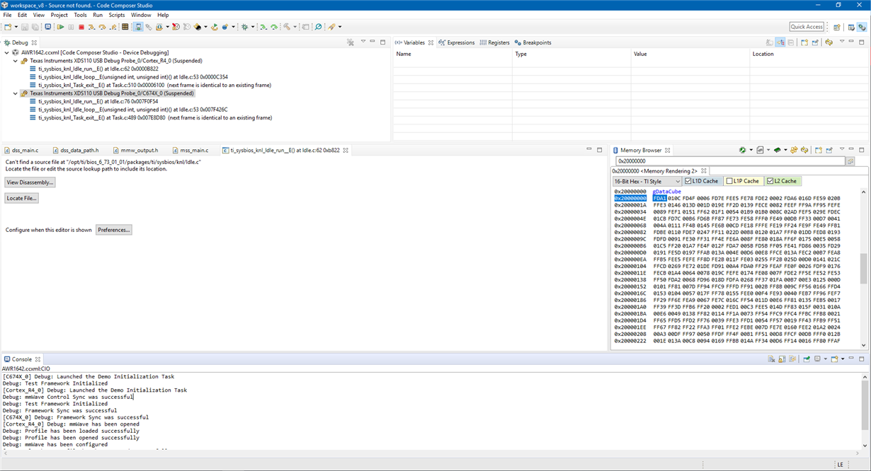
    After you start the mem_capture test in CCS by running both the MSS and DSS cores, you should see the following messages printed in the CCS console:

    [C674X_0] Debug: Launched the Demo Initialization Task
    Debug: Test Framework Initialized
    [Cortex_R4_0] Debug: Launched the Demo Initialization Task
    Debug: mmWave Control Sync was successful
    Debug: Test Framework Initialized
    Debug: Framework Sync was successful
    [C674X_0] Debug: Framework Sync was successful
    [Cortex_R4_0] Debug: mmWave has been opened
    Debug: Profile has been loaded successfully
    Debug: Profile has been opened successfully
    Debug: mmWave has been configured
    [C674X_0] Debug: Profile has been opened successfully
    [Cortex_R4_0] Debug: Profile has been started successfully

    After you see these messages, you can pause both the MSS and DSS cores in CCS. After you do this, make sure to select the DSS core and then open the Memory Browser by going to "View"-->"Memory Browser". Using the .map file that is provided in the same folder, you can look at the .map file for the DSS and find out the memory location where the radar cube is being stored.

    As a quick note, the radar cube starts at the beginning of L3 memory on the DSS. You can also search for ".dataCubeMemory". This will give you the memory location and you then can copy right into the memory browser in CCS. Make sure to start all addresses with 0x-------- and then fill in the addresses from the .map file. You can then export the radar cube using the built-in export functionality of CCS and save it to a text file.

    There is no need to use TeraTerm for this example. You can use CCS and examine the structures like "gMemCaptureMCB". gCaptureProfileCfg is not a command.

    Regards,
    Kyle

  • Dear Kyle,

    First of all, profound thanks for the very valuable help. I have acted as per your advice and guidance which I could not not find in any documentation. I have succeeded in getting the memory file. But there are a few related questions which I request you to please reply before I consider that my issue has been fully resolved.

    I request you to please comment / reply each point individually:

    1)   For those like who like me do not know where to find the map file, please open the text file titled ( xwr16xx_mem_capture_dss ) at location C:\ti\mmwave_sdk_03_02_00_04\packages\ti\drivers\test\mem_capture\xwr16xx .

    Kyle, I have attached the relevant file and from this file, I have obtained the address " 20000000 " for the start of L3 memory and/or for ( .dataCubeMemory ) . I hope it is correct, however, can you please have a quick look at the attached file and confirm that i have determined the correct address.


    Then i added 0x as advised by you and i used the address " 0x20000000 " in CCS Memory Browser.


    2)   I have referred an earlier document i.e. SDK User Guide Product Release 1.1.0 section 3.3.3 para 5(e) for storing the content from Memory Browser. (File attached)

    I have used 16-bit Hex TI style, is it correct ?

    I have used data size 0x20000, is it correct ?


    3)   There is a MATLAB script given in SDK 1.1.0.2 at location C:\ti\mmwave_sdk_01_01_00_02\packages\ti\demo\xwr16xx\capture\gui . I have attached the script as well.


    This MATLAB script is part of SDK 1.1.0.2 and it can be used with Capture Demo of the same SDK 1.1.0.2.

    Can I use the above MATLAB code with mem_capture Test in SDK 3.2.0.4 as well ? Will it give correct results ?

    4)   In earlier Capture Demos (for example in SDK 1.1.0.2), the user could give SensorStart command as his own time of choice.

    In Test mem_capture in SDK 3.2.0.4, when does the sensor start and when does sensor stop putting data in L3 Memory Radar Cube and can we control the Sensor Start and Sensor Stop at our own wish ?

    5)    In SDK 1.1.0.2 Capture Demo, the data for one frame (comprising 128 chirps) could be stored (You may refer 3.3.3 # 5a of SDK Guide 1.1.0 , file attached above) . How much data can be stored in memory using the current Test mem_capture in SDK 3.2.0.4 ?

    6)    In SDK 1.1.0.2 Capture Demo, the user could either input the desired configuration through CLI or the configuration was hard coded (You may refer 3.3.3 # 3 and 5a of SDK Guide 1.1.0 , file attached above)

    In the current Test mem_capture in SDK 3.2.0.4, is the radar configuration hard-coded? If yes, then what are the configuration parameters / details ?
    In addition, for Test mem_capture in SDK 3.2.0.4, can the user input its own desired configuration also (of course it may have some limits like frame length, maximum number of chirps etc) ? If yes, then how can the user input its own desired custom configuration in Test mem_capture in SDK 3.2.0.4 ?


    Thank you for your patient reading and thanking you in advance for additional guidance.

  • Hi, again Kyle,

    I was trying to attached the 3 files as i mentioned in my above message but due to some system error, I could not attach them so I sent the above message without the attached files.

    Sorry for this inconvenience.

    But i have included the detailed location for every one and I hope you will not have much difficulty in locating them form your own database.

    However, I am sorry again for the inconvenience caused.

    Regards

  • Hi, Kyle,

    Can I please request feedback and advice on my above messages dated 11th July, 2019 ?

    Regards

  • Hi Kyle,

    After I did the men-capture test inCCS,the following messages appeared on the screen .Is this ok?

    Cheers

    XU

  • XU,

    If you are able to successfully run the mem_capture test in CCS, you should see the following console messages:

    [C674X_0] Debug: Launched the Demo Initialization Task
    Debug: Test Framework Initialized
    [Cortex_R4_0] Debug: Launched the Demo Initialization Task
    Debug: mmWave Control Sync was successful
    Debug: Test Framework Initialized
    Debug: Framework Sync was successful
    [C674X_0] Debug: Framework Sync was successful
    [Cortex_R4_0] Debug: mmWave has been opened
    Debug: Profile has been loaded successfully
    Debug: Profile has been opened successfully
    Debug: mmWave has been configured
    [C674X_0] Debug: Profile has been opened successfully
    [Cortex_R4_0] Debug: Profile has been started successfully

    This is what my CCS looks like:

    Regards,

    Kyle

  • Hi Kyle,

    What can I do to get this interface?Can you give me a brief description?

    Regards,

    XU

  • XU,

    You need to first flash the CCS debug image that is included in the SDK installation for SDK version 3.2 using the Uniflash tool.

    It is found here: C:\ti\mmwave_sdk_03_02_00_04\packages\ti\utils\ccsdebug

    After this image is flashed, you launch the .ccxml configuration for AWR1642 and connect to the two target cores. You then load the binary executable files for the mem_test.

    These files are found here: C:\ti\mmwave_sdk_03_02_00_04\packages\ti\drivers\test\mem_capture\xwr16xx

    Then you run both cores after the two images are loaded.

    If you run this correctly, then you will see the screen that I uploaded in my previous post.

    Regards,

    Kyle

  • Hi,

    Kyle

    Thanks for your reply.But my SDK version is 2.0,is it ok?

    Cheers,

    XU

  • XU,

    Yes, you can follow the same steps using SDK v2.0. The files are located in the same folders that they are found in SDK v3.2

    Regards,
    Kyle

  • Thanks for your help.

  • Hi,

    Kyle

    I am using the IWR 6843, I wonder to know where can find the .ccxml file for IWR 6843

    Regards,

    zhenyuan

  • Hi zhenyuan,

    the .ccxml file is generated in CCS according to the SDK User Guide. Have a look at the CCS development mode section.

    Best Regards

  • This thread has been resolved and is now considered closed. For any other questions, please create a separate thread with your question.

    Regards,
    Kyle

  • Hi,

    Thanks for your help!

    Best Regards