This thread has been locked.

If you have a related question, please click the "Ask a related question" button in the top right corner. The newly created question will be automatically linked to this question.

AWR1642BOOST: What's the Rx data arrangement for mem_capture for SDK3.2 with 2TX and 4Rx ?

Part Number: AWR1642BOOST
Other Parts Discussed in Thread: DCA1000EVM, AWR1642

Hi,

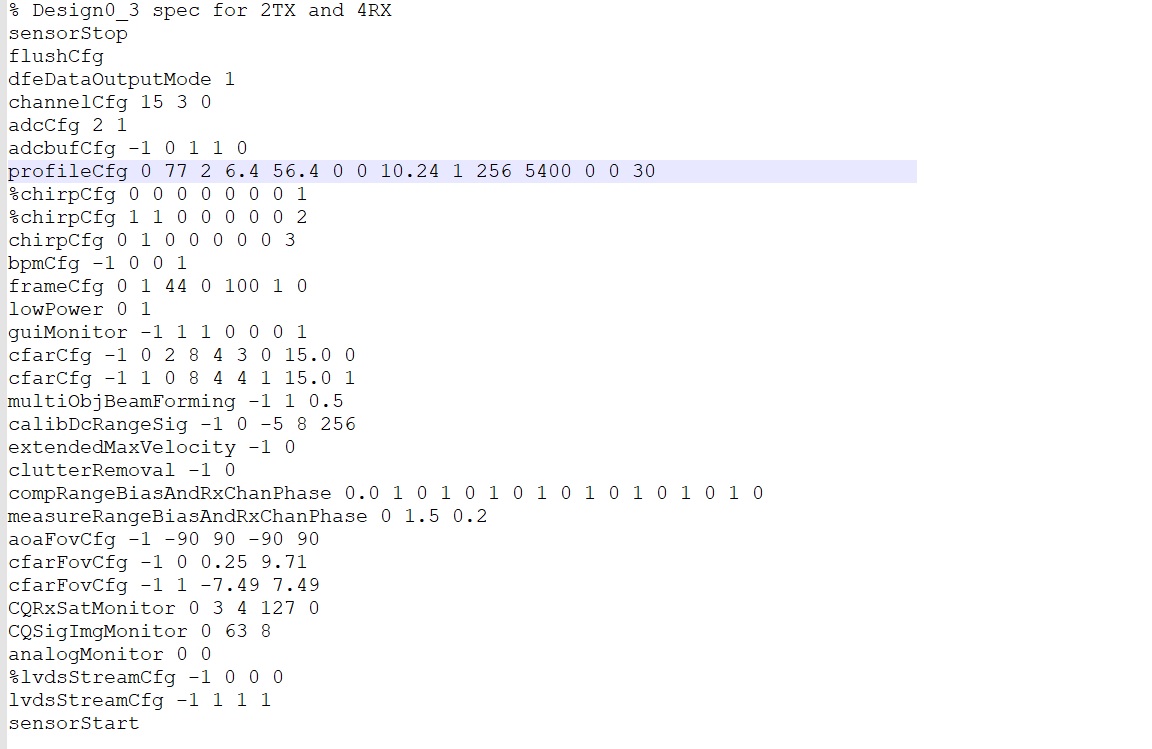
  I can get the raw ADC data from mem_capture with 2Tx & 4Rx  from DSS gDataCube and save it to .dat file with SDK ver3.2.   

  The data format is supposed to be IQ format, 16-bit ADC, complex x1, and non-interleaved mode.

   The setup procedure and test are shown as follows.
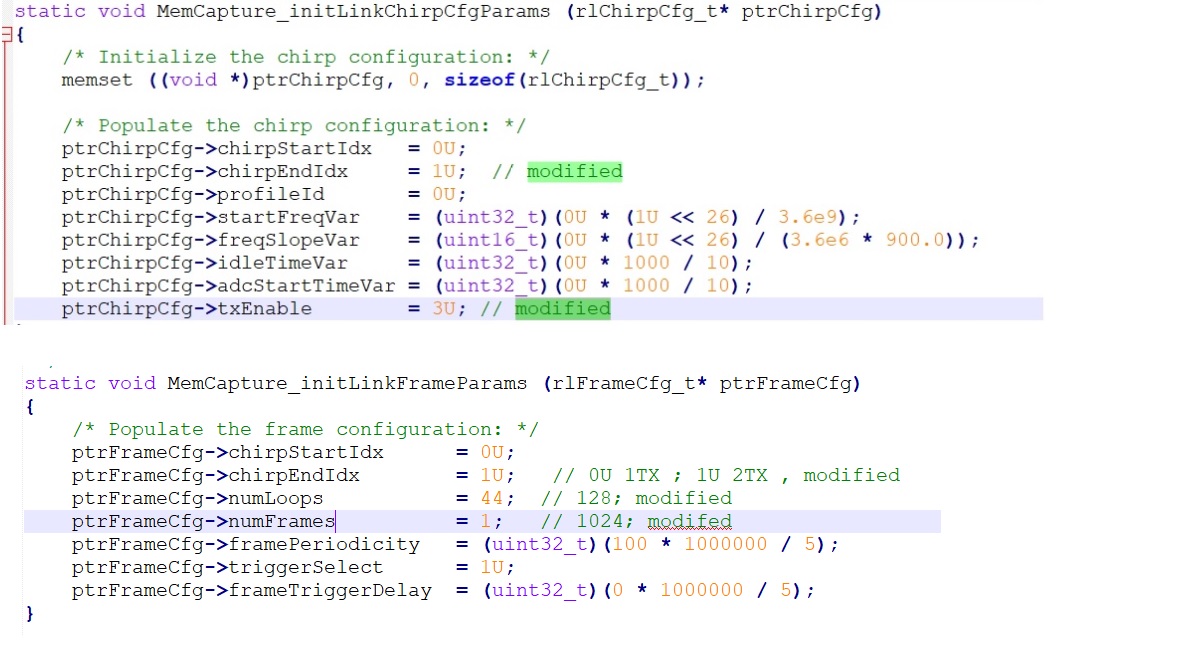
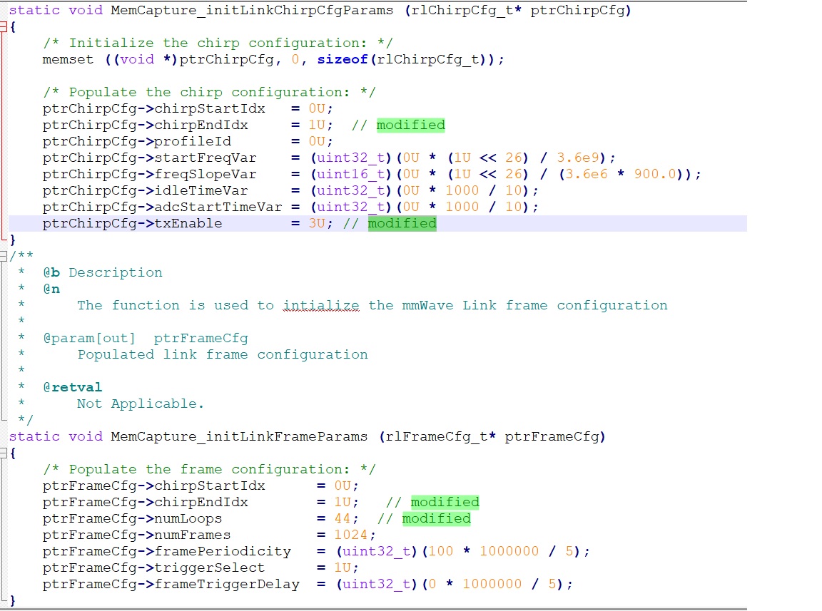
   Step1: modify mss.c 


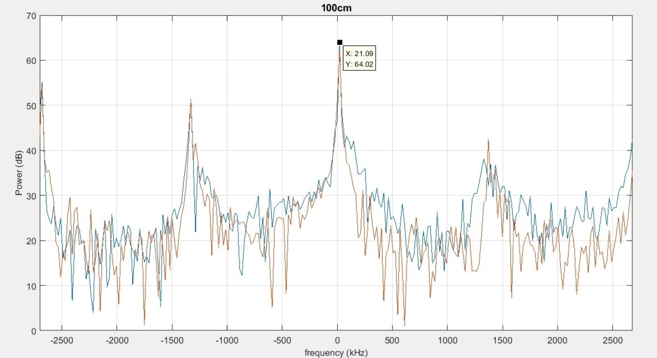
            Step 2: build mem_capture , run mss and dss code , then show gDataCube for capturedraw data


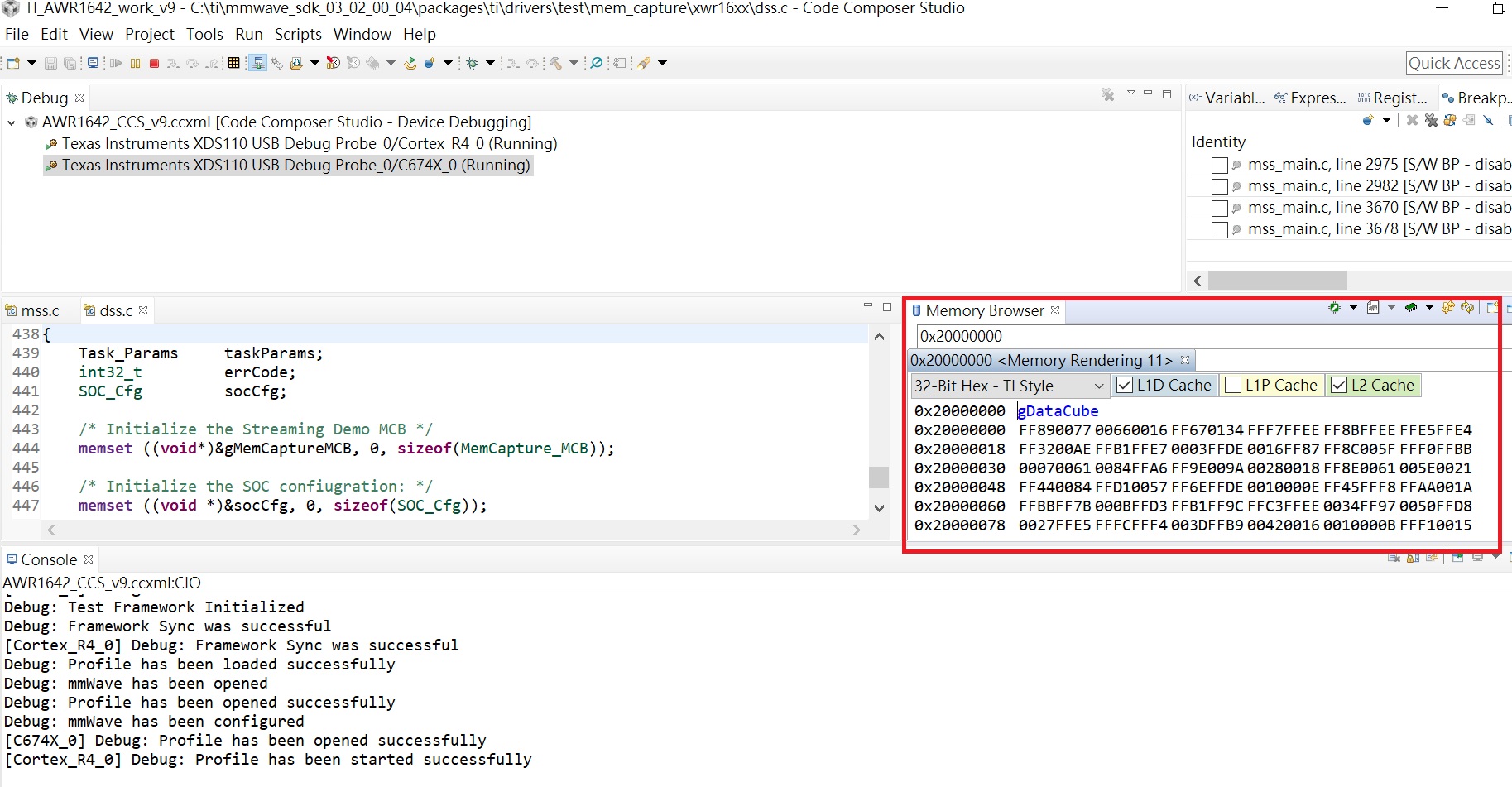
   Step 3: save gDataCube to xxx.dat file


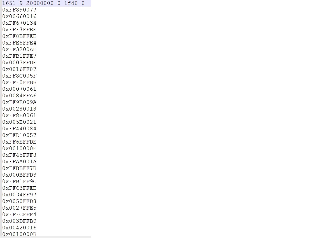
  Question 1:  The captured data sequence, xxx.dat,  is Q1.1 or Q1.2 in the following?

        Q1.1  Rx0(0), Rx1(0), Rx2(0), Rx3(0), Rx0(1), Rx1(1), RX2(1), Rx3(1).......RX0(N),Rx1(N), RX2(N), Rx3(N)   or

        Q1.2  Rx0(0), Rx0(1), .....Rx0(N), Rx1(0), RX1(1), ...RX1(N), RX2(0),RX2(1),...,RX2(N), Rx3(0), RX3(1), ... Rx3(N)

 Question 2: The data arrangement is Tx1 first to Rx0~Rx3 , then Tx2 to Rx0 ~Rx3 ,  next data is changed to next Tx1 to Rx0~Rx3, then Tx2 to Rx0~Rx3  .... ?

  Thanks for you help.

    Best Regards,

   A-Kai

  • Hi A-Kai,

    Please refer these app-notes for the captured data format.

    http://www.ti.com/lit/an/swra581b/swra581b.pdf

    http://www.ti.com/lit/an/swra555/swra555.pdf

    Regards,

    Jitendra

  • Dear Jitendra,

      Thanks for your quick response. I had understood the data arrangement such as all of the RX0 data is stored sequentially, followed by all of the RX1 data based on these 2 pdf file.

      But I still have a question as follow.

      Q1 : For TDM mode , the data sequence for a RX , ex. RX0,  whether its captured data sequence are Tx1 -> Tx2 -> Tx1->Tx2 ... until all chirps completed in a frame , then repeat above sequence for next frame,  until all frames defined in ptrFrameCfg->numFrames are stored in memory ?

      Best Regards,

       A-Kai

  • Hi,

    Section 4 and 5 of this app-note describes the Rx data order.

    Please have a look at above appnotes.

    Regards,

    Jitendra

  • Dear Jitendra,

       Based on the modified mss.c of above 1st post except for ptrFrameCfg->numFrames = 1, and the data format of section 4 of swra581b, we got the 2Tx and 4Rx data to analyze with matlab. 

       The data sequence is supposed to be  1st_chirp_Tx0 sample1(IQ) , sample2(IQ) ... sample256(IQ), 1st_chirp_Tx1 sample1(IQ), sample2(IQ)...,sample256(IQ), 2nd_chirp_Tx0 sample1(IQ), sample2(IQ)...,sample256(IQ), 2nd_chirp_TX1 sampl11(IQ), ..., until 44x2 chirps for RX0, then Rx1 -> Rx2->Rx3 within 1 frame size.

       But we analyze the 1st_chirp_Tx0 256 sample & next 256 sample at 5400 kps with FFT, and the result is not like as the one from demo visualizer with same configuration (single target with distance=1m). 

      1. Demo Visualizer test:

         1.1 The CLI config file for demo visualizer is as follow.


       1.2. demo visualizer result: ok, peak will be around 1m distance.


      2. Matlab test from mem_capture  data:  something wrong

         2.1 modified mss.c, like as above CLI config file:


       2.2 mem_capture result with matlab: something wrong , not similar with demo visualizer around 1 m distance.

              peak= 21.09 KHz

              C= 3*10^8 m/s

              freq_slop= 10.24 MHz/us for 2Tx_4Rx

            The range result will become  (21.09*10^3 * 3*10^8 )/ (2* 10.24*10^12) = 0.309 m, not around 1m (test distance).


      Question: The error is from

                       (1) the misunderstanding data sequence

                            or

                       (2) the modified config of mem_capture mss.c ?

       Best regards,

       A-Kai

  • Hello, have you solved the problem? I'm stuck here too.

  • I also have a question about how mmWave_Demo_Visualizer interacts with memory capture in ccs, which can be further described as how to control the start and stop of acquisition. Thank you

  • Hi,

      We still have the issue which has not been fixed.

      We had re-tested the mem_capture code with 1Tx_1Rx, 1TX_2Rx, 1TX_4Rx and 2Tx_1Rx, 2TX_2RX, 2TX_4Rx to confirm the issue. 

     We found if the Rx number is increasing such as 2Rx, 4Rx, the beat freq(distance) will be reduced by 1/2 and 1/4 compared with 1Rx.

     Pls refer to :  https://e2e.ti.com/support/sensors/f/1023/t/834888

     We are verifying the issue with DCA1000EVM.

    Best Regards,

     A-Kai

  • Thank you for your reply and Wishing you success .I have a problem that seems to have blocked my process. I tried to modify the parameter configuration of chirp and frame in the mss.c file. After recompiling and loading into the DSP and arm cores, this did not seem to have been successfully configured, but it did. I checked the DSS and mss. map files and found that the data length was not there Change, what should I do?

    Best wishes

  • If you are looking to make changes to the mem_capture example, you need to make sure that you first run the setenv.bat file that is provided in the SDK and set it for AWR1642.

    You can find that file here: C:\ti\mmwave_sdk_03_02_00_04\packages\scripts\windows

    Then you can invoke the top level makefile from the following file location: C:\ti\mmwave_sdk_03_02_00_04\packages\ti\drivers\test\mem_capture

    Please refer to the SDK User's Guide documentation for more information about working with the SDK within the command prompt in Windows.


    Regards,

    Kyle