Part Number: TDC7200
Other Parts Discussed in Thread: TDC1000
Hi Team,
The TDC7200 is in working mode 2 for use with the TDC1000. Use the oscilloscope to observe trigger, start, stop, and the pin has a clear pulse waveform.
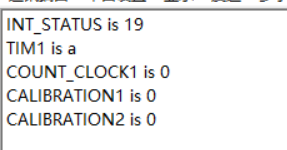
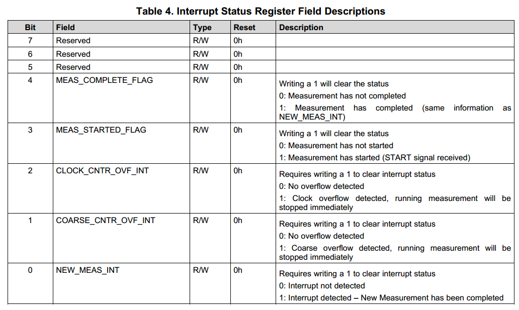
Read the Interrupt Status Register (address = 02h) register of the TDC7200 and the result is 0x19. But when reading TIME1: Time 1 Register (address: 10h) and CLOCK_COUNT1: Clock Count Register (address: 11h), the two registers always have a result of 0.
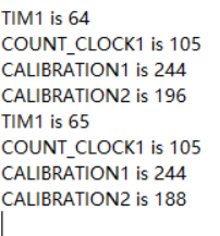
When he uses mode 1, there will be normal values in the TIM1 register. Once changed to mode 2, the TIM1 register is always 0. The values in the CALIBRATION1 and 2 registers are also always 0.