This thread has been locked.

If you have a related question, please click the "Ask a related question" button in the top right corner. The newly created question will be automatically linked to this question.

DRV425: DRV425

Part Number: DRV425

Hello,

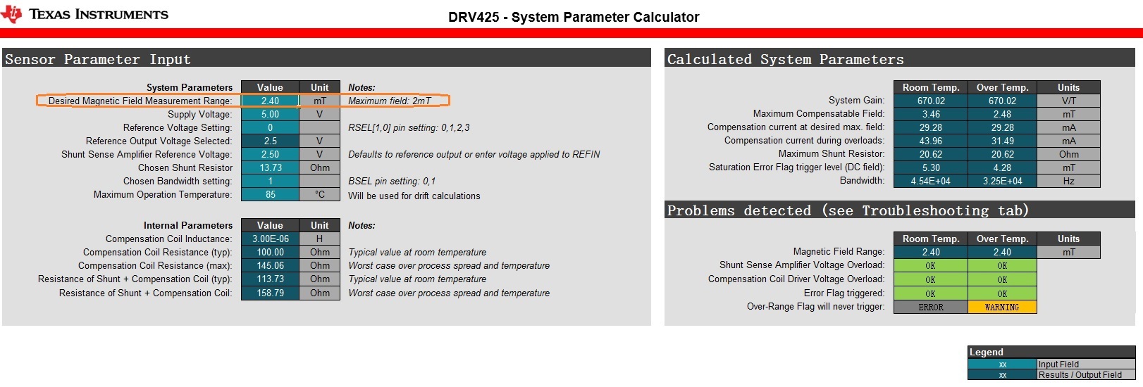
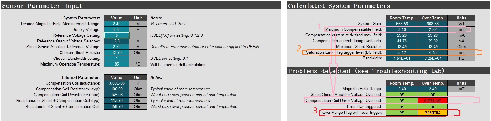
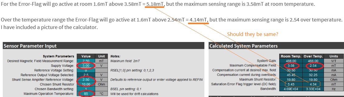
From datasheet of DRV425, the max sensor range is +/-2mT, the saturation magnetic field is above +/-3.6mT.

Is that possible it is used to measure magnetic field bigger than 2mT, such as 2.4mT?

Below is the calculation, it seems ok based "system parameter calculator."

But why "max field: 2mT" is noted?  What problems would be met if it's used to measure magnetic field bigger than 2mT?

  • Hello User,

    Thanks for using the forum to answer your question.  The answer is yes the DRV425 can measure above 2mT but you need to be carefull with the voltage and temperature you will be using it as you can see the Compensation Coil resistance changes with temperature and limits your range.  Also VCC and Vref will change the range as well.  The calculator is a great place to see these limitations.  The 3.6mT has to do with the Error flag getting activated.

  • Hello Javier,

    Thanks for your quick reply!

    So 2mT~3.6mT is still active measurement range?

    What do you mean "The 3.6mT has to do with the Error flag getting activated." ?

  • Hello User,

    The DRV425 cannot measure much over 2mT but you need to make sure it can be measured for your conditions based on the calculator.  There is a tab in the calculator that you can see the range for your conditions.

    Any time the field is above approximately 3.6mT the sensor is saturated and the ERROR goes active low to advice you the sensor is out of range.  This is for the example of 2mT being the maximum field that can be compensated in the datasheet.  This value is 1.6mT above the maximum compensated field.  

    So for example if you are only going to 85°C and you have a Rshunt of 10Ω and will be using 5V and a Reference of 2.5V  your maximum compensation field at room is 3.58mT at room temperature and 2.54mT over temperature.

    For the Error-Flag will go active at room 1.6mT above 3.58mT = 5.18mT, but the maximum sensing range is 3.58mT at room temperature.

    Over the temperature range the Error-Flag will go active at 1.6mT above 2.54mT = 4.14mT, but the maximum sensing range is 2.54 over temperature.  I have included a picture of the calculator.

  • Hello Javier,

    It's clearer for me now.

    Below calculation is based on the extreme conditions/worst case at my side.

    I still have 3 questions:

    1. The "maximum compensatable field" is limited by railing of the  compensation coil driver, right?

    2. The " saturation error flag trigger level (DC field)" is 5.12mT and 4.15mT seperately. But not (3.1mT + 1.6mT) and (2.22mT + 1.6mT), as you metioned in last mail?

        Does  the "saturation error flag trigger level (DC field)" means the Error-Flag in your last mail - "For the Error-Flag will go active at room 1.6mT above 3.58mT = 5.18mT, but the maximum sensing range is 3.58mT at room temperature."

    3. When " Over-Range Flag will never trigger"  is "Error" or " Warning",  the OR will not be active. But why?

  • Hello user,

    1. Yes the driver is limited by the VDD and GND pin.  Also be aware your Reference is not centered between VDD and GND.  I know it is not much but one direction could get larger field capability than the other.

    2. For your values you are correct.  The numbers I mentioned were with my input parameters in the excel calculator.  

    Yes saturation error flag trigger means Error-Flag will go active.

    3. The Over-Range Flag is only active when the Output of the Difference amplifier is saturated.  The warning means that you may not saturate your Difference amplifier because you could saturate your flux gate first or saturate your compensation coil driver before you max out the input of the difference amplifier. 

  • Hello Javier,

    It's clear for questions 1 and 3.

    But for question 2,  still in your example, what i ask is: "Saturation Error Flag trigger level" = "Maximum Compensatable Field" +1.6mT? 

  • Hello,

    You are correct that they are different.  I looked into the calculations and the "Maximum Compensation Field" using some guard band with the compensation drive ability.  This is due to the compensation drive not being able to drive all the way to VDD or GND and giving a 0.1V guard.  The Saturation Error Flag trigger level value did not use this guard band and it added 1.7mT to the value.  I have to dig into why this was done in the calculator or if this was done for a guard.  I can research that but I do not think it will be useful for two reasons.

    1. The maximum compensation field will vary with temperature.
    2. The Saturation Error Flag trigger is a typical specification and could vary a little.  This flag is only meant to signal to the user that the output voltage will not be valid.

  • Hello Javier,

    Yes, I understand the "Maximum Compensatable Field" and the reason of vary with temperature, based on below temperature.

    But, for "Saturation Error Flag trigger level", my questions are:

    1) as you metioned - " Any time the field is above approximately 3.6mT the sensor is saturated".

        so, can I say, in your example, the Error Flag does not work when 3.6mT is applied?

    2) the Error Flag works when 5.43mT at room temperature in your example?

        still, 5.34mT ≠ 3.58mT + 1.6mT, whichi is "Saturation Error Flag trigger level" ≠ "Maximum Compensatable Field" +1.6mT?

  • Hello,

    1) You are correct.  I was mentioning this when 2mT is the max compensation and was reading off the datasheet example of 3.6mT 

    2)The calculator uses the "Compensation Current during overload" to calculate the "Saturation Error Flag trigger level".  Which is not the "Maximum Compensation Field" in the calculator.   This is because it is expected that the "Maximum Compensation field" will still be in the linear range and you can still get a valid measurement.  The "Compensation Current during overload" expects the max current during the overload.  Also the calculator uses 1.7mT instead of 1.6mT as a buffer.

  • Hello Javier,

    Thanks, it is clear now.