This thread has been locked.

If you have a related question, please click the "Ask a related question" button in the top right corner. The newly created question will be automatically linked to this question.

IWR6843AOPEVM: Do the receivers have Automatic Gain Control?

Part Number: IWR6843AOPEVM
Other Parts Discussed in Thread: AWR1642

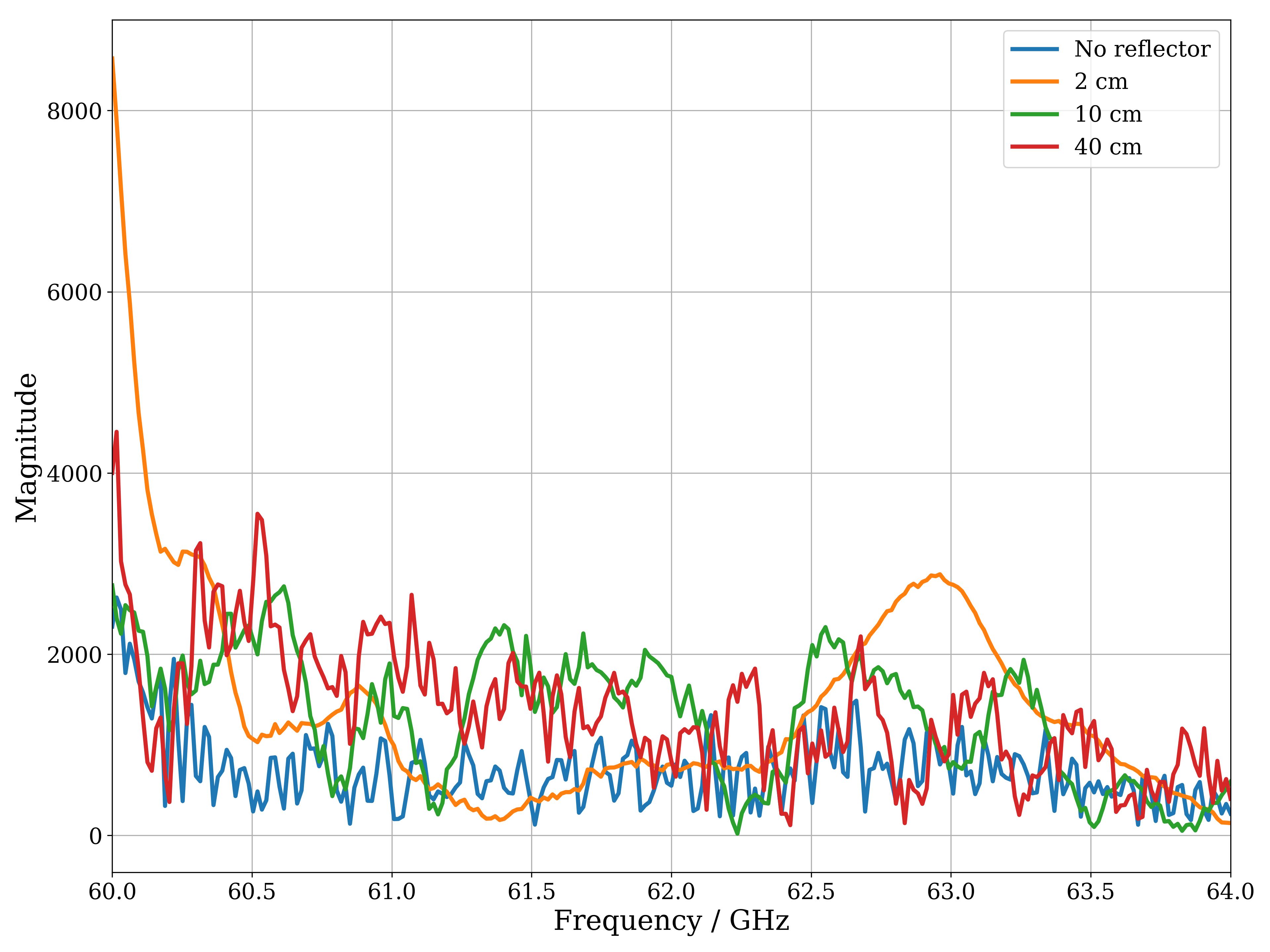
We are capturing the raw ADC data from the IWR6843AOPEVM. Without any objects present the magnitude of the signal is much the same as when there is a reflector close to the sensor.

Do the receiver channels have AGC and if so, can we turn it off?

Another contributor asked the same question for the AWR1642 and he was told there was no AGC, but his case didn't provide a solution to his problem. 

On the Ti Training website, mmWave Training Series, the block diagram for the AWR16xx and IWR16xx devices in  documents "Ti Automotive mmWave Sensors Device Overview" and "Ti Industrial mmWave Sensors Device Overview" both show a block "AGC/DC est." applied to the filter and gain stages of the receiver. I can't find any other documentation for this block.

Thanks,

Ian

  • Hello Ian,

       Could you please post your observation? i.e. At what distance you are seeing higher magnitude? What chirp configuration is used? Is this measured on mmWave studio or OOB demo or custom demo demo configuration?  

    Receivers do not have AGC hardware block, But AGC functionality could be developed in the application i.e. Receivers have the gain controls knobs and we have APIs to detect the receiver saturation and based on that gain controls could be applied.

    Thanks and regards,

    CHETHAN KUMAR Y.B.  

  • Hi Chethan,

    Thanks for the information and the prompt reply. We're going to try a little experiment then get back to you with the results. Please don't close the case just yet, if that's OK.

    Regards,

    Ian

  • Hi Chethan,

    The graph below shows the magnitude of the received signal on Rx0 for a chirp, averaged the data over 100 frames, with a 10cm x 10cm copper pcb reflector placed at varying distance from the IWR6843AOPEVM.
    We don't understand why the magnitude is not varying with the reflector distance, if there isn't any gain normalization going on. We would be grateful if you could explain it and suggest how to make the received magnitude vary with distance.

    The mmWave configuration was obtained from the mmWave Demo Visualiser, using the default settings but with only Tx0 enabled and with the frame rate set to 1 frame/s.
    We are reading a single chirp of Raw ADC Data straight from the start of the Raw ADC buffer and outputting it to the serial port immediately after the default processed data (we're not using a DVM1000).
    Otherwise the firmware is the OOB demo.

    % ***************************************************************
    % Created for SDK ver:03.02
    % Created using Visualizer ver:3.2.0.0_AOP
    % Frequency:60
    % Platform:xWR68xx_AOP
    % Scene Classifier:best_range_res
    % Azimuth Resolution(deg):60 + 60
    % Range Resolution(m):0.044
    % Maximum unambiguous Range(m):9.02
    % Maximum Radial Velocity(m/s):1.21
    % Radial velocity resolution(m/s):0.16
    % Frame Duration(msec):1000
    % Range Detection Threshold (dB):15
    % Doppler Detection Threshold (dB):15
    % Range Peak Grouping:enabled
    % Doppler Peak Grouping:enabled
    % Static clutter removal:disabled
    % Angle of Arrival FoV: Full FoV
    % Range FoV: Full FoV
    % Doppler FoV: Full FoV
    % ***************************************************************
    sensorStop
    flushCfg
    dfeDataOutputMode 1
    channelCfg 15 7 0
    adcCfg 2 1
    adcbufCfg -1 0 1 1 1
    profileCfg 0 60 975 7 57.14 0 0 70 1 256 5209 0 0 30
    chirpCfg 0 0 0 0 0 0 0 1
    frameCfg 0 0 16 0 1000 1 0
    lowPower 0 0
    guiMonitor -1 1 1 0 0 0 1
    cfarCfg -1 0 2 8 4 3 0 15 1
    cfarCfg -1 1 0 4 2 3 1 15 1
    multiObjBeamForming -1 1 0.5
    clutterRemoval -1 0
    calibDcRangeSig -1 0 -5 8 256
    extendedMaxVelocity -1 0
    lvdsStreamCfg -1 0 0 0
    compRangeBiasAndRxChanPhase 0.0 -1 0 1 0 -1 0 1 0 -1 0 1 0 -1 0 1 0 -1 0 1 0 -1 0 1 0
    measureRangeBiasAndRxChanPhase 0 1.5 0.2
    CQRxSatMonitor 0 3 5 121 0
    CQSigImgMonitor 0 127 4
    analogMonitor 0 0
    aoaFovCfg -1 -90 90 -90 90
    cfarFovCfg -1 0 0 8.92
    cfarFovCfg -1 1 -1.21 1.21
    sensorStart

    Regards,

    Ian

  • Hi Chethan,

    Sorry for the delay, I accidentally posted this to myself the first time.

    The graph below shows the magnitude of the received signal on Rx0 for a chirp, averaged the data over 100 frames, with a 10cm x 10cm copper pcb reflector placed at varying distance from the IWR6843AOPEVM.
    We don't understand why the magnitude is not varying with the reflector distance, if there isn't any gain normalization going on. We would be grateful if you could explain it and suggest how to make the received magnitude vary with distance.

    The mmWave configuration was obtained from the mmWave Demo Visualiser, using the default settings but with only Tx0 enabled and with the frame rate set to 1 frame/s.
    We are reading a single chirp of Raw ADC Data straight from the start of the Raw ADC buffer and outputting it to the serial port immediately after the default processed data (we're not using a DVM1000).
    Otherwise the firmware is the OOB demo.

    % ***************************************************************
    % Created for SDK ver:03.02
    % Created using Visualizer ver:3.2.0.0_AOP
    % Frequency:60
    % Platform:xWR68xx_AOP
    % Scene Classifier:best_range_res
    % Azimuth Resolution(deg):60 + 60
    % Range Resolution(m):0.044
    % Maximum unambiguous Range(m):9.02
    % Maximum Radial Velocity(m/s):1.21
    % Radial velocity resolution(m/s):0.16
    % Frame Duration(msec):1000
    % Range Detection Threshold (dB):15
    % Doppler Detection Threshold (dB):15
    % Range Peak Grouping:enabled
    % Doppler Peak Grouping:enabled
    % Static clutter removal:disabled
    % Angle of Arrival FoV: Full FoV
    % Range FoV: Full FoV
    % Doppler FoV: Full FoV
    % ***************************************************************
    sensorStop
    flushCfg
    dfeDataOutputMode 1
    channelCfg 15 7 0
    adcCfg 2 1
    adcbufCfg -1 0 1 1 1
    profileCfg 0 60 975 7 57.14 0 0 70 1 256 5209 0 0 30
    chirpCfg 0 0 0 0 0 0 0 1
    frameCfg 0 0 16 0 1000 1 0
    lowPower 0 0
    guiMonitor -1 1 1 0 0 0 1
    cfarCfg -1 0 2 8 4 3 0 15 1
    cfarCfg -1 1 0 4 2 3 1 15 1
    multiObjBeamForming -1 1 0.5
    clutterRemoval -1 0
    calibDcRangeSig -1 0 -5 8 256
    extendedMaxVelocity -1 0
    lvdsStreamCfg -1 0 0 0
    compRangeBiasAndRxChanPhase 0.0 -1 0 1 0 -1 0 1 0 -1 0 1 0 -1 0 1 0 -1 0 1 0 -1 0 1 0
    measureRangeBiasAndRxChanPhase 0 1.5 0.2
    CQRxSatMonitor 0 3 5 121 0
    CQSigImgMonitor 0 127 4
    analogMonitor 0 0
    aoaFovCfg -1 -90 90 -90 90
    cfarFovCfg -1 0 0 8.92
    cfarFovCfg -1 1 -1.21 1.21
    sensorStart

    Regards,

    Ian

  • Ian,

        For the above chirp configuration range resolution is 4.4cm. 

    For such close distance (2cm and 10cm), leakage from Tx to Rx would dominate in terms of reflected power as compared to power reflected from the metal plate. Typically this may spill over few range bins. Object 2cm/10cm falls in DC and few range bins would be suppressed by Tx, Rx leakage. 

    Typically, for reference and calibrations  Corner reflectors are used (For example shown below), This will have known RCS for calibration as compared to metal from PCB reflector. https://www.miwv.com/trihedral-corner-reflectors/

    You could try higher distance with the stronger reflector to see reflected image higher from noise floor. Also you could use more chirps/frame to increase the SNR and reduce the noise floor.

    Thanks and regards,

    CHETHAN KUMAR Y.B.