This thread has been locked.

If you have a related question, please click the "Ask a related question" button in the top right corner. The newly created question will be automatically linked to this question.

IWR6843: Pinmux settings & device coding for I2C/SPI usage

Part Number: IWR6843
Other Parts Discussed in Thread: MMWAVEICBOOST, TIDEP-0091, IWR1443, UNIFLASH, IWR1642

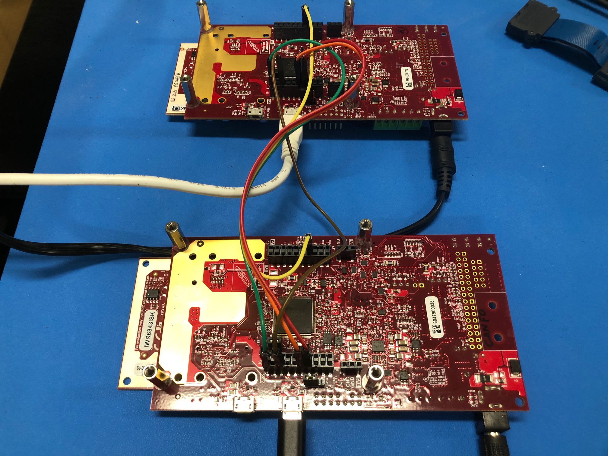
I'm using mmWave IWR6843.

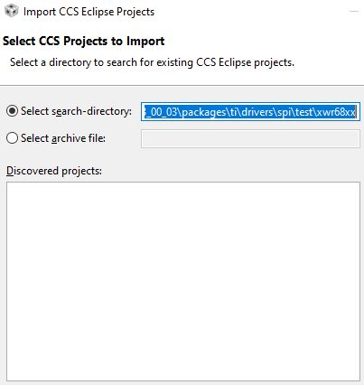
I saw in TI website has PixMux software but Windows OS does not allow me to install it, so I may need to use Cloud PinMux Tool. But I see no tutorial of Cloud PixMux Tool and the correlation between PinMux tool setting and device code.

1. Is it necessary to write some register codes or hardware modification related to pinMux in order to use SPI, I2C? I checked the document swru546b, but there's no information about it. As I know, if we do wrong on pinMux, the board will be broken. Please provide me with documents and share real application experience on it,

I read IWR6843 datasheet and see some infor such as PINCNTL ADDRESS

I2C_SCL is 0xFFFFEA74

I2C_SDA is 0xFFFFEA78

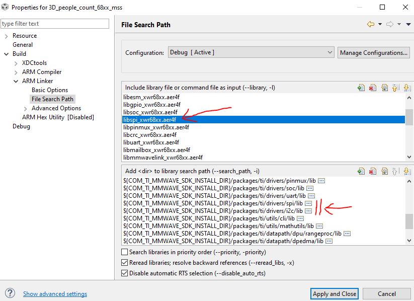
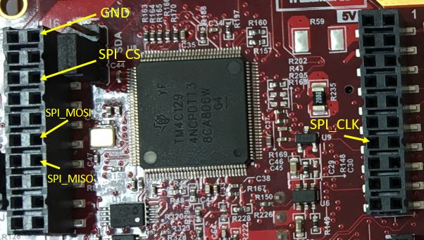
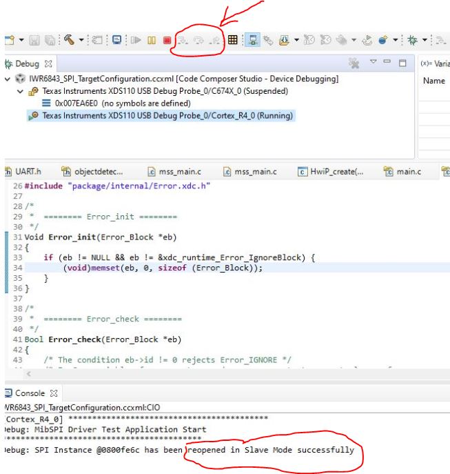
SPIA_CLK is 0xFFFFEA14, SPIA_CS_N, SPIB_CLK... Are SPIA & SPIB 2 SPI ports? Are these 2 SPI ports initially enabled ready for use or we have to do something to enable it? I checked SPI & I2C reference code in SDK, but I don't see any correlation between pinmux and SPI, I2C. Please explain in more details.

Based on PINCNTL ADDRESS, please show me how to write code for SPI/I2C corresponding to PinMux settings.

2. By the way, can u introduce me any adapter device (SPI/I2C to USB converter) to connect IWR6843 to PC via SPI/I2C pins? I found some FTDI ICs FT2232C (for SPI), FT232H (for I2C). Is it better to connect IWR6843 to Rapsberry Pi 3 via SPI/I2C directly rather than using SPI/I2C-to-USB converter to general-purpose PC? If I connect IWR6843 to Rapsberry Pi 3 model B+ via SPI/I2C, the voltages are the same to connect without having to use any adapter, right?

3. If I use FTDI IC for SPI/I2C to USB converter, how can I send data from IWR6843 to PC through FTDI IC? Do I need to write my own code for FTDI IC or there's an API? 

If I don't care the IC brand, can you suggest me some SPI/I2C to USB converter which provides me with full source code to send data?

4. If I use Rapsberry Pi 3 to get data from IWR6843 via SPI/I2C, is there any difference between TI SDK in Windows OS and Linux? Can I use the same TI source code on different OS? If not, please give me link to download SDK, and all TI required tools on Linux in order to test with Rapsberry Pi 3.

  • Hi,

    Please download and install MMWAVE SDK.  In the path below in the SDK directory, there are examples you can review to understand how to setup the peripherals.

    mmwave_sdk_03_xx_xx_xx\packages\ti\drivers

    the appnote linked below also has SPI implemented in the SW package

    http://www.ti.com/lit/ug/tidud26b/tidud26b.pdf.

    Charles O

  • Hi Charles,

    1. Because UART data transfer rate is low, so I want to connect radar board to PC via SPI/I2C for higher speed. But if we still use MSP432 to connect to PC via UART port, PC still receive data as slow as UART rate, right? So it's not different from connecting IWR6843 directly to PC via UART. Since IWR6843 also has UART port, what's the point of using MSP432 as a bridge between IWR6843 & PC if it does not help increase data transfer rate than UART?

    2. I see in TI SDK has spiTest.cpp, it mentions FTDI Spi interface. Do I need to write code separately for FTDI IC? Please tell me how to connect IWR6843 to PC by using FTDI SPI/I2C. 

    3. Besides, you haven't replied my question about the correlation between pinmux setting and SPI/I2C device code and the way of assigning register address for SPI/I2C pins in device code.

  • Hector Ta said:
    1. Because UART data transfer rate is low, so I want to connect radar board to PC via SPI/I2C for higher speed. But if we still use MSP432 to connect to PC via UART port, PC still receive data as slow as UART rate, right? So it's not different from connecting IWR6843 directly to PC via UART. Since IWR6843 also has UART port, what's the point of using MSP432 as a bridge between IWR6843 & PC if it does not help increase data transfer rate than UART?

    if the intention is to connect to the PC directly via SPI, you can use the other USB port on the MMWAVEICBOOST. Please see section 2.4.1 of the users guide.

    http://www.ti.com/lit/ug/swru546b/swru546b.pdf

    Please not that the OOB demo, mmWave visualizer and other applications we provide currently only support UART,

    Hector Ta said:
    2. I see in TI SDK has spiTest.cpp, it mentions FTDI Spi interface. Do I need to write code separately for FTDI IC? Please tell me how to connect IWR6843 to PC by using FTDI SPI/I2C. 

    When the FTDI is connected using the USB shown above, it appears on the device manager as a COM port. The FTDI on the MMWAVEICBOOST is programmed, you only need to install the driver in other to see the COM port 

    Hector Ta said:
    3. Besides, you haven't replied my question about the correlation between pinmux setting and SPI/I2C device code and the way of assigning register address for SPI/I2C pins in device code.

    Please reviews the examples in the SDK, it shows how to setup the pinmux and various peripherals. 

  • Hi Charles,

    I modified mss_main.c code, then added SPI lib to mss project path but the compile still got error. Please tell me a way to solve it.

  • Hi Charles,

    I got less compiling error by adding xwr68xx_spi_mss.xer4f in the path C:\ti\mmwave_sdk_03_03_00_03\packages\ti\drivers\spi\test\xwr68xx to the project.

    Previously, I got 13 compile errors. After added xwr68xx_spi_mss.xer4f, now I only see 4 errors. Not sure whether this is better or not. But even if I don't use SPI function and remove all SPI commands, I still have these 4 errors after adding xwr68xx_spi_mss.xer4f to my project. If I don't add it, I only got compile error when I use SPI commands.

    How to solve it? I expect I can use SPI/I2C within this week, but I got stuck at library linking even though it seems to be easy.

    1. Here's the error after I added xwr68xx_spi_mss.xer4f

    error: "could not be statically or dynamically linked null: file "C:/ti/mmwave_sdk_03_03_00_03/packages/ti/drivers/spi/test/xwr68xx/xwr68xx_spi_mss.xer4f" could not be statically or dynamically linked 3D_people_count_68xx_mss C/C++ Problem

    2. Here's the error without xwr68xx_spi_mss.xer4f, I only added libspi_xwr68xx.aer4f in the path C:\ti\mmwave_sdk_03_03_00_03\packages\ti\drivers\spi\lib

  • Are you trying to build the SPI test code, or are you trying to link the SPI driver into an existing CCS project?  Nothing within the SDK builds within CCS by default - only gmake makefiles are used. The SDK user guide gives full instructions on how to build via gmake.  So if you want to rebuild the SPI test code, use gmake.

    If you are trying to include the SPI driver into your CCS project, then I question why are you trying to include SPI test code?

     -dave

  • Hi woodall,

    My Manager wants me to prove that I can make SPI function works well on IWR6843 EVM. So I need to demo it on a PC, maybe via GUI or data stored in csv/excel. But GUI provided by TI can only demo via UART, so I guess it's not suitable for my purpose. So I have these questions:

    1. Is there any way to test SPI function of IWR6843 EVM and still connect its XDS110 port to PC USB port to show a demo of SPI read/write?

    2. If it's mandatory to use a bridge circuit board? I read TIDEP-0091 that described connection between IWR1443 & MSP430 launchpad, but I don't have MSP430 now. Is there any document or sample code to communicate Raspberry Pi, Arduino with IWR6843? 

    3. In the future, I may purchase MSP432 launchpad, please share me the SPI communication code and UART GUI for the project demo similar to TIDEP-0091.pdf file.

  • >1. Is there any way to test SPI function of IWR6843 EVM and still connect its XDS110 port to PC USB port to show a demo of SPI read/write?

    Sure, you can simply flash the pre-built SPI example program.  The program uses the USB UART to display information and to request sub-test numbers. What test(s) you can run depends on what you connect to the carrier card.  Probably the easiest way to show the SPI is working is by using an SPI protocol tester. You can also edit/rebuild the example code to only perform the tests you are interested in, and in the SPI mode you are interested in.

    >2. If it's mandatory to use a bridge circuit board? I read TIDEP-0091 that described connection between IWR1443 & MSP430 launchpad, but I don't have MSP430 now. Is there any document or sample code to communicate Raspberry Pi, Arduino with IWR6843?

    No, but you do need something that understands SPI.  I have used two 6843 EVMs, and connected the two carrier cards with breadboard jumper wires. TIDEP-0091 uses an MSP432.  You can also use any other kind of board such as a Raspberry Pi or Beagle Bone, you just need to find out how to connect the wires and configure the device for an SPI mode that is compatible with the SPI mode used on the 6843 EVM.  Here are the carrier card connections. You can refer to the board schematics to see which pins are which:

    >3. In the future, I may purchase MSP432 launchpad, please share me the SPI communication code and UART GUI for the project demo similar to TIDEP-0091.pdf file.

    This code is already available with the design guide material here: www.ti.com/.../tidcde2

  • Hi woodall,

    1. Can you give me the SPI code to read/write data between 2 IWR6843 EVM? I'm doing 3D people counting. It'd be great if you have SPI code for 2 IWR6843 EVMs or similar EVM for my application. 

    If SPI data transfer is successful, we can still display tracking on GUI via UART of 1 EVM without having to design new GUI or write SPI code on MSP432/Pi.

    Anyways, I'm still concerned about the way to demo on GUI. e.g. We have EVM A & B. We write data from A to B via SPI. After B finished SPI reading, B send data to PC via UART. How can I know that B didn't send tracking data by itself? Because both boards are working. Maybe SPI write from A was failed but GUI still get data from B. Do I need to store SPI data read in a buffer then send it from B to GUI to know whether SPI works well?

    2. The link you sent to me is not available to download. Please upload on Dropbox or Google Drive and send me another link. Of course, if you can send me code as #1 query, I don't need to use MSP432 anymore. But it's still good to have both solution.

  • Attached are two zip files.  xwr6843_mmw_spi_demo_src.zip provides files to drop into the 68xx mmw demo MSS folder (MSS only).  xwr68xx_spi_slave_testcode_src.zip contains files to drop into C:\ti\mmwave_sdk_03_0x_0x_0x\packages\ti\drivers\spi\test\xwr68xx.  I strongly suggest making copies of the original files so that you can compare them to see the differences.  You will need to rebuild both the demo, which sends demo output to SPI, and the test code, which receives the SPI transfers and displays counts of received messages. Follow the SDK user guide's instructions to build.

    xwr6843_mmw_spi_demo_src.zip

    xwr68xx_spi_slave_testcode_src.zip

  • Hi woodall,

    Thanks for prompt reply.

    As I see, spi_slave_testcode is only to read data from spi_demo_src. So the spi_slave_testcode will be flashed on EVM that connects to PC, right?

    1. In spi_slave_testcode , Test_oobRangeProfile does System_printf(). Does it print out valid_data_cnt and valid_hdr_cnt? Where will those cnt be displayed on PC? 

    2. You said that I should put spi_slave_testcode in C:\ti\mmwave_sdk_03_03_00_03\packages\ti\drivers\spi\test\xwr68xx

    then rebuild that folder. But I couldn't import any data in this path on CCS.

    3. In spi_demo_src, I see function MmwDemo_transmitProcessedOutput(), it's to transmits detection data over UART. So there're two EVMs A & B.

    EVM A is flashed spi_slave_testcode and connect to EVM B via SPI.

    EVM B is flashed spi_demo_src, and connect to PC via USB port

    am I right?

    I don't see any pinmux setting for UART and function for UART transfer. How can PC get data from EVM B?

    4. Can you send me all files for 3D people counting with 2 EVMs communicate via I2C then transfer data to PC via UART? 

  • Hi woodall,

    I'm still waiting for your reply last Friday. Besides, I see in spi_slave code you sent to me, it used test_spi_read. But it's supposed to work as a slave, so it should write data to master, right?

    I can't import project in that path C:\ti\mmwave_sdk_03_0x_0x_0x\packages\ti\drivers\spi\test\xwr68xx for spi_slave. Do we just copy code from main.c to main_css.c in the project workspace?

    Please answer my questions last time also. Thank you indeed!

  • >1. In spi_slave_testcode , Test_oobRangeProfile does System_printf(). Does it print out valid_data_cnt and valid_hdr_cnt? Where will those cnt be displayed on PC? 

    If you run in the CCS debugger, they will appear in the console window.  If you run connected to TeraTerm, they will appear there.

    >2. You said that I should put spi_slave_testcode in C:\ti\mmwave_sdk_03_03_00_03\packages\ti\drivers\spi\test\xwr68xx then rebuild that folder. But I couldn't import any data in this path on CCS.

    As I mentioned before, everything within the SDK builds from gmake.  Please check the SDK's user guide for instructions on re-building drivers and driver example code.  You can still load the executable from the debugger and run it there (doing this requires flashing the CCS debug image to the device).

    >3. In spi_demo_src, I see function MmwDemo_transmitProcessedOutput(), it's to transmits detection data over UART. So there're two EVMs A & B.

    The code should send output to the SPI peripheral.  The second EVM is running spi_slave_testcode and receives the sent messages.

    >4. Can you send me all files for 3D people counting with 2 EVMs communicate via I2C then transfer data to PC via UART? 

    We do not have an example that does this. You would need to code this on your side using the i2c example code as a start.

      -dave

  • Hi woodall,

    You said "The code should send output to the SPI peripheral.  The second EVM is running spi_slave_testcode and receives the sent messages." -> Do u mean we can test SPI on both EVMs? I thought our model is EVM1 (slave) write data to EVM2 (master) via SPI, EVM2 write data to PC via UART. If GUI on PC shows target tracking normally means SPI signal is good.

    As you described, EVM1 can also connect to a PC, by TeraTerm we can see sent message on that PC? I see your spi_slave code does not include UART read/write function, can TeraTerm show sent message on EVM1?

  • Hi Dave,

    Plus questions in 4/30, today I want to ask extra things. Here're what I've done before asking you:

    - I flashed ccsdebug.bin on IWR6843.

    - I generated 2 xer4f files: first is xwr68xx_spi_mss.xer4f in the path C:\ti\mmwave_sdk_03_03_00_03\packages\ti\drivers\spi\test\xwr68xx, second one is  xwr68xx_mmw_demo_mss.xer4f in the path C:\ti\mmwave_sdk_03_03_00_03\packages\ti\demo\xwr68xx\mmw. Is the 1st file to flash on EVM1 as a slave and 2nd one to flash on EVM2 as master?

    - I copied the main.c in your spi_master folder to replace the one in the path C:\ti\mmwave_sdk_03_03_00_03\packages\ti\drivers\spi\test\xwr68xx. Then I generated a new xwr68xx_spi_mss.xer4f file. After that, I created ccxml file in CCS and loaded the MSS program, chose xwr68xx_spi_mss.xer4f. But I'm still unclear about the way to see SPI result.

    1. Do I need to flash 3D_people_count or HVAC bin file after finished all steps above or just keep the setting of ccsdebug.bin? I tried to run GUI connected to IWR6843 but it didn't work. It seemed not to work with ccsdebug.bin flashed before. So I couldn't test SPI function. 

    I'm a little confused about xwr68xx_spi_mss.xer4f and xwr68xx_mmw_demo_mss.xer4f. In order to test SPI function between master & slave, we must run these files on CCS Debug mode, but how can we run xer4f Debug mode in both EVMs in one PC? Do we need 2 PC to do it?

    2. How to check whether SPI works well by CCS in Debug mode after loaded xer4f file by using 1 PC via GUI?

    3. If I want to do SPI communication without running CCS in Debug mode, how to create my own code from TI SDK and burn bin file on IWR6843? I tried to link TI library to CCS project, but it showed: #10010 null... xer4f not built. That's why I have to test SPI by CCS in Debug mode. I prefer running program without CCS Debug mode. Because I need to give my customers my program. They are only able to run the program without much effort. If I use xer4f to run in CCS Debug mode, it's inconvenient for them.

  • Hi Hector,

    Many of your questions will be answered by examining the code.  The modified demo configures SPI as Master, and the modified test code configures SPI as Slave.  The slave writes it's test messages to System_printf(), which goes to "standard out" (see the function Test_oobRangeProfile). Standard out when running in CCS is the console window.  Standard out when flashed sometimes is directed to the USB (depending on the program), which will appear via the UART.  If it doesn't, you will need to change the System_printf statement in Test_oobRangeProfile to write to the UART instead.

    Once the two EVMs are flashed with their respective images, these are the steps you will need to do:

    1) Connect the two carrier cards with the 4 jumper wires as previously shown.

    2) Set the DIP switches on the carrier cards to use the LaunchPad headers:

    1 - off

    2 - on

    3 - off

    4, 5 - on

    6, 7 - off

    8, 9 - on

    10, 11 - off

    12 - on

    3) Attach the USB cables from both carrier cards to a PC.

    4) Attach power to both carrier cards.

    5) Open teraterm windows to both.

    6) Send the CLI configuration to the EVM flashed with the demo.

    7) Output will begin coming from the EVM flashed with the test code.

  • Hi Dave,

    Thanks for your very clear response. Is there any way to rebuild bin file of spi_slave_test in the driver path? C:\ti\mmwave_sdk_03_03_00_03\packages\ti\drivers\spi\test\xwr68xx 

    1. I did as instruction in user guide but can only generate bin file in demo folder for SPI master. Gmake command only generate xer4f file for spi_slave, but Uniflash only flash bin file. So I need a bin file for SPI slave.

    I tried to copy spi_slave main.c into demo folder but it couldn't be built. Currently, I can only use gmake to get bin file for SPI master.  I created a new project in CCS then copied code from spi_slave main.c into it. Then I can build successfully, but each time doing always have to handle "library linking" issue. So i prefer a way to generate bin file directly in TI SDK path to avoid library not linked problem. Please tell me how to generate bin file for SPI slave directly in SDK path, not only xer4f file.

    2. What's the purpose of MCPI_Initialize() & MCPI_setTestResult() ? When I put them in my project mss code, mss can't be built. So I had to remove them, without those MCPI functions, project compile well. That's why I asked you how to generate spi_slave bin file by gmake directly in SDK driver folder to avoid this compile issue.

    3. Besides, your photo last time was blurred. So I attach my photo here. Do we need to connect GND, CS, CLK, MOSI, MISO pins of 2 EVMs together as position in my photo?  As i know, we only need to connect 4 SPI pins for communication. Why do you connect GND of 2 EVMs? Please confirm whether my photo is correct and explain more about pin GND, 3v3 and 5V. When do we need to connect them? 

    4. When do we set S1 switch as below?

    S1.1 OFF
    S1.2 ON
    S1.3 OFF
    S1.4 ON
    S1.5 ON
    S1.6 ON
    S1.7 ON
    S1.8 OFF
    S1.9 OFF
    S1.10 ON
    S1.11 ON
    S1.12 ON

    I guess it's only for normal mode via XDS110 port, without SPI, right? How about S1 switch settings for I2C and CAN-FD?

    - By the way, if I connect IWR6843 EVM to Arduino or Rapsberry Pi via SPI, do I need to use any voltage converter board to avoid device broken? I'm not sure about the voltage difference between them. It'd be great if I can connect them directly the same way as between 2 IWR6843 EVMs. But I'm concerned since IWR6843 Input voltage is 5 V, while Arduino Uno is 6-12V. It may cause EVM broken.

  • Hi Dave,

    I tested SPI slave in CCS Debug mode. When I pressed "Step into" to SPI_open(), it showed "SPI Instance @0800fe6c has been reopened in Slave Mode successfully". But after that it seemed to keep running in a forever loop and didn't print out System_printf("Valid hdr: %d Valid data: %d Invalid msg: %d\n", valid_hdr_cnt, valid_data_cnt, invalid_msg_cnt);

    You can see my photo that CCS can't click on "Step into" button after SPI_open() and no more printf message was printed out.

    So I don't know whether the Test_spiRead() works well or not. 

    I tried to modify code like this after SPI_open() was successful:

    if(Test_spiRead(handle, SPI_TEST_MSGLEN, (void *)rxBuf, 0U) == 0)
    {
      System_printf("SPI Instance %p transfer successfully\n", handle);
    }

    In SPI.h, I also modified MIBSPI_RAM_MAX_ELEM = 128. But it didn't print out any message to confirm SPI transfer is good. In master EVM, I flashed bin file of demo code you sent to me last time. I want to see SPI transfer successful message on SPI slave. Please tell me how to make this works well.

  • The SPI read function will wait forever until a message arrives.  With the test code I provided, you can start it first and it will loop until you start the demo on the master device that sends messages to it.

  • HI Dave.

    I modified your test code by removing while(1), then I put right after SPI_open()

    if (SPI_transfer() ==0) { System_printf("SPI transfer ok"}. And I powered on Master EVM with demo code to write data, but no message was received. How to enable SPI_write in Master EVM? I think after flashed demo code, it'll automatically send data to slave. Please help me enable the SPI_write in demo code.

    I tested like this:

    EVM1(Slave) runs in CCS Debug mode with xer4f spi_test_code.

    EVM2(Master) flashed bin file from demo code.

    Do I need to operate both EVMs in CCS Debug mode? I think we only need to run EVM1 in debug mode, EVM2 can still write data to EVM1 automatically. If my thoughts was wrong, please tell me how to handle it. I only know to connect one EVM to CCS. Anyways, in real application we don't run in Debug mode, so please tell me how to make EVM write/read both cases with/without CCS

  • Hector, did you start the demo program?  When you power it on, it will initialize but wait for you to send a configuration to it.  You can either copy/paste a profile to TeraTerm (eg. ti\demo\xwr68xx\mmw\profiles\profile_2d.cfg) or use the demo visualizer to do the same.  Please refer to the SDK documentation for more details.
     
  • Hi Dave,

    Can I use visualizer of 3D_people_count toolbox? I tried it but it didn't work. Then I used TI cloud visualizer to connect to my Master EVM, but it was stuck at "device connecting". I waited for a long time but device couldn't connect. I'm wondering whether it's an error of TI cloud?

    Besides, if I use 3D_count visualizer, do I need to choose SDK_out_of_box_demo for testing? I chose SDK_out_of_box_demo with profile_2d.cfg as you said, but spi_slave still didn't receive any message. After that, I tried TI visualizer cloud as I mentioned above, but serial port didn't connect. 

     Please tell me another way to enable SPI_write in demo code without TI cloud visualizer.

  • Dave,

    Currently, I can connect to TI visualizer cloud. But I can only adjust configuration on the interface. How to send my cfg from PC to device via TI cloud?

    Since I can't send cfg successfully on TI cloud. I used HVAC code and added SPI_write() into it. Then I ran 3D_people_count GUI to send profile_2d.cfg, I also tried to send sense_and_direct_68xx.cfg to EVM, but slave EVM still loop forever after SPI_open() was successful and can't read message.

    I checked all SPI & GND wires, their connection is still good. Is it possible that your code didn't assign matched SPI address for 2 EVMs? Where can I check that information?

    Is there any way to SPI_write without having to send configuration? All demo visualizer and 3D_count GUI didn't make SPI_write work after I sent profile_2d.cfg and many other cfg. 

    I also tried Teraterm but that tool is weird. After connected serial port at baud rate 115200, I pressed on send file to send cfg to EVM, but it stopped at 0.2% and did nothing. If it's ok for you, please show me video tutorial of teraterm sending cfg to Master EVM and implement SPI_write from EVM1 to EVM2.

    No matter which tool(Teraterm/TI visualizer), please show me a tutorial (video is better) to solve this SPI read/write problem. 

  • Hi Hector,

    If you have not familiarized yourself with the basics such as running the out of box (mmw) demo and driver example code, I suggest that you do that before attempting something that is more difficult like trying to connect two EVMs with SPI with different programs.

    WRT to running the demo, the simplest way is to start TeraTerm with the proper serial port settings and hit enter in the window to get the demo's prompt.  Then edit profile_2d.cfg, copy everything and paste it into TeraTerm.  If there are failures in sending the commands you need to add character and line delays in the TeraTerm settings until it can send everything successfully.

    WRT to your connections between the EVMs, I don't think your picture is correct.  Go back and look at my picture.  It is not blurry; the jumper wires connect identically on both boards, so use the EVM on the left as the example as it is very clear.

      -dave

  • Hi Dave,

    - I tested demo with HVAC & 3D_count many times before, so I'm familiar with it. 

    - How to do Teraterm serial port settings? For example, we have 2 port UART: COM4, Data: COM3. Which one should I use to connect via Teraterm? At which baudrate (115200 or 926000)?

    - My photo is correct, but I only take photo of 1 EVM. Then I connect corresponding pins of EVM1 to EVM2. Why do you think it's incorrect? I'm a little confused whether it's the cause of my SPI write failure, even though I think my connection must be correct because it's easy.

  • >How to do Teraterm serial port settings

    Please read section 3.3 of the SDK's user guide.  You want to use the "User" COM port.  TeraTerm will allow you to change the settings when you select a port number.

    >My photo is correct

    In my photo, you can see that I am using J6 pins 2, 6, 12 and 14 for GND, SPI_CS, SPI_MOSI and SPI_MISO respectively. These are on the Left side of J6.  The arrows in your photo point to pins 1, 3, 11 and 13 on the Right side of J6.

  • ok. I thought pins of J5,J6 correspond to document. I double-checked and did the wiring correctly now. 

    About Cfg sending, I connected to UART port via Teraterm, set at baudrate 115200. There's 2 issues:

    1. When I flashed your demo code, then sent Cfg via Teraterm, it always showed: Error -1

    Please help me check the demo code you sent to me last time to handle this issue.

    2. When I modified original demo code by myself, added SPI function, Cfg sent successfully, it showed : Init Calibration Status = 0x1e

    but SPI_read() in slave EVM is still wait for message forever. Last time you said I just need to send Cfg to device, then SPI_read will get message. Why it still can't read now?

    3. I modified your spi_slave code. You said after SPI_open on EVM2, it wait for SPI_write from EVM1. If EVM1 hasn't sent cfg and data, EVM2 will wait forever. So I replaced SPI_read in while(1) by SPI_write and system_printf("SPI transfer ok"). But it still didn't print any message after SPI_open. Why is it so weird? Can't I make SPI_write on spi_slave_test?

            handle = SPI_open(0, &params);
        if (handle == NULL)
        {
            System_printf("Error: Unable to open the SPI Instance\n");
            return;
        }
        System_printf("Debug: SPI Instance %p has been reopened in Slave Mode successfully\n", handle);
        spiMsg = (spiDataMsg*)&txBuf[0];
        memset(spiMsg, 0, 128);
        spiMsg->msgId = SPI_RANGE_HEADER;
        spiMsg->dataLen = sizeof(MmwDemo_output_message_header);
        spiMsg->seqNo   = 0;
    	
    for (i=0; i < sizeof(MmwDemo_output_message_header)/2;i++)
    	{
    		uint16_t *buf = (uint16_t *)&header;
     		spiMsg->data[i] = buf[i];
    	}
    	
    		
       while(1)
        {			
            spi_Write (handle, (uint8_t*)spiMsg, SPI_TEST_MSGLEN);
    		if(spi_Write (handle, (uint8_t*)spiMsg, SPI_TEST_MSGLEN) == 0)
    		{
    			System_printf("Debug: SPI tranfer successfully\n");
    		}
        }

  • Hi Dave,

    Your spi_slave code is only to read data. How can I transfer SPI_read data to GUI via UART? Besides, your spi_slave code can only test SPI_read by simple message and counter. Do I need to send Cfg on both Master & Slave EVM?

    As my understanding, EVM1 needs to get Cfg, then it can do SPI_write. Then, EVM2 get target tracking data by SPI_read. Does EVM2 need to get Cfg before sending data via UART?

    Please send me the extra code to add into your previous spi_slave code to get target tracking data frame by SPI_read (not only message and counter) and display on GUI UART.

  • >How can I transfer SPI_read data to GUI via UART? Besides, your spi_slave code can only test SPI_read by simple message and counter.

    You will need to add code to the slave program to take the data read from SPI and write it to the UART.  To do this, look at how the demo configures the UART and writes data to it.  In this case, you would need to use the DATA UART that is configured at 921600 baud.

    >As my understanding, EVM1 needs to get Cfg, then it can do SPI_write. Then, EVM2 get target tracking data by SPI_read. Does EVM2 need to get Cfg before sending data via UART?

    No. Clearly, the slave program is a simple program that only reads the SPI.  It does nothing else.

  • Dave,

    1. What's the command from Master to request Slave write data to it?

    I see in demo code, Master has 2 lines

    spiParams.u.masterParams.slaveProf[0].chipSelect = 0;
    spiParams.u.masterParams.slaveProf[0].ramBufLen = MIBSPI_RAM_MAX_ELEM;

    How can Master know the address of Slave? What's the meaning of chipSelect = 0 and ramBufLen = MIBSPI_RAM_MAX_ELEM above? chipSelect = 0 means Master command Slave to write data to it, right?

    If I have 2 slaves, how can I let Master request data from each Slave corresponds to their own address? In other words, how can Master know it's getting data from which Slave? Or we don't need address but only use delay() to separate each Slave?

    As I know, we need to keep CS pin (Chip select) low when we want to read data from the slave. How to assign address for Slave and enable it to write to Master in case we use over 2 Slaves? Please give me exact code. I checked your level_sense_demo used IWR443 & MSP432, but I don't see any Chip select =0 command being sent from MSP432 to Slave in main_thread.c program. I only see perform_calibration() return data, then uart_send_string() will get data to demo on GUI, right? I don't know how MSP432 commands IWR443 to write data to it in your code. Please tell me the code of uart_send_string() and  spi_get_transfer(). I only see their prototype, not declaration, so it's not clear. I figured out spi_get_transfer in msp_spi.c and uart_send_string() in msp_uart.c, but how can main_thread.c can run if you don't put those functions into it?

    Maybe I not only use 2 TI EVMs communication method. I also need to use other boards such as Rapsberry Pi or MSP432 as a Master to request IWR6843 slave to send data to it, so I need to know how to send command from Master to Slave.

    2. Where's the GUI code to get data from MSP432 and demo on PC?

    3. Do you have dss & mss + SPI function source code of IWR1642? I only have 1 IWR6843 now. So I need to use 1642 as a replacement. If you have, please send to me.

  • 1) What's the command from Master to request Slave write data

    The SPI peripheral provides standard SPI functionality.  Please refer to the driver's documentation here:

    file:///C:/ti/mmwave_sdk_03_04_00_03/packages/ti/drivers/spi/docs/doxygen/html/index.html

    and the driver source (header structs, example function calls, etc) for more details.

    2) Where's the GUI code to get data from MSP432

    The TI design is here: https://www.ti.com/tool/TIDEP-0091

    and the software is here: https://www.ti.com/lit/zip/tidcde2

    3) Do you have dss & mss + SPI function source code of IWR1642?

    The DSP does not typically interface to external peripherals. For xWR1642, you can use the SPI driver test code for the 1642, *or* you can transplant the SPI function calls from the xWR6843 demo that I provided into the 1642 demo, depending on what you need to do.  I do not have anything else that is not part of a demo or SDK.

  • Hi Dave,

    I see your code defines rxBuf and txBuf. In case I want to transfer TLV data, should I use a fixed size array as a buffer? Besides, I don't know whether the Master can read data from Slave all at once or not.

    1. Do I need some delay (i don't know what delay function in TI SDK) or something else?

    2. How to arrange the data reading on Master by SPI_read in a correct sequence? I'm concerned that header and TLV frame data can be mixed up.

    Below is my code of Master and Slave.

    Master code for SPI_read and UART_write to GUI

    static void SPI_to_UART
    (
        SPI_Handle      spiHandle,
        UART_Handle     uartHandle,
        DPC_ObjectDetection_ExecuteResult   *result,
        MmwDemo_output_message_stats        *timingInfo
    )
    {
    //Read data from slave
    spi_Read(spiHandle, (void *)rxBuf, SPI_DATA_BLOCK_SIZE);
    ....// 
    UART_write(uartHandle, (void *)rxBuf, SPI_DATA_BLOCK_SIZE);
    }
    

    I don't know how to handle rxBuf and transfer TLV tracking data to GUI via UART_write in correct sequence (header, data frame TLV index...). Please tell me how to make it work.

    Slave code for SPI_write. I modified original demo code, not your demo code. I replaced UART_write by SPI_write with the same input buffer. So I don't use txBuf here.

    If you don't want to look at the huge code of MmwDemo_transmitProcessedOutput() below, here's my brief idea. Please confirm if my method for Master & Slave write/read is correct.

    //UART_writePolling (uartHandle,(uint8_t*)&tl[tlvIdx], sizeof(MmwDemo_output_message_tl));  // original demo code used this line
    //UART_writePolling (uartHandle,(uint8_t*)&header, sizeof(MmwDemo_output_message_header));  // original demo code used this line
    	
    //SPI write head and TLV index from Slave to Master
    spi_Write (spiHandle, (uint8_t*)&header, sizeof(MmwDemo_output_message_header));   
    spi_Write (spiHandle, (uint8_t*)&tl[tlvIdx], sizeof(MmwDemo_output_message_tl));

    static void MmwDemo_transmitProcessedOutput
    (
    SPI_Handle      spiHandle, UART_Handle uartHandle, DPC_ObjectDetection_ExecuteResult *result, MmwDemo_output_message_stats *timingInfo ) { SPI_Handle spiHandle; MmwDemo_output_message_header header; MmwDemo_GuiMonSel *pGuiMonSel; MmwDemo_SubFrameCfg *subFrameCfg; uint32_t tlvIdx = 0; //uint32_t tlvIdx_spi = 0; uint32_t index; uint32_t numPaddingBytes; uint32_t packetLen; uint8_t padding[MMWDEMO_OUTPUT_MSG_SEGMENT_LEN]; MmwDemo_output_message_tl tl[MMWDEMO_OUTPUT_MSG_MAX]; int32_t errCode; uint16_t *detMatrix = (uint16_t *)result->detMatrix.data; DPIF_PointCloudCartesian *objOut; cmplx16ImRe_t *azimuthStaticHeatMap; DPIF_PointCloudSideInfo *objOutSideInfo; DPC_ObjectDetection_Stats *stats; //spiDataMsg *pTestMsgOut; //uint16_t seqNo; //uint16_t dc_offset; //int rangeLength,i; /* Get subframe configuration */ subFrameCfg = &gMmwMssMCB.subFrameCfg[result->subFrameIdx]; /* Get Gui Monitor configuration */ pGuiMonSel = &subFrameCfg->guiMonSel; /* Clear message header */ memset((void *)&header, 0, sizeof(MmwDemo_output_message_header)); //Read data from slave //spi_Read(spiHandle, (void *)rxBuf, SPI_DATA_BLOCK_SIZE); //pTestMsgOut = (spiDataMsg *)&rxBuf[0]; /****************************************************************** Send out data that is enabled, Since processing results are from DSP, address translation is needed for buffer pointers *******************************************************************/ { detMatrix = (uint16_t *) SOC_translateAddress((uint32_t)detMatrix, SOC_TranslateAddr_Dir_FROM_OTHER_CPU, &errCode); DebugP_assert ((uint32_t)detMatrix!= SOC_TRANSLATEADDR_INVALID); objOut = (DPIF_PointCloudCartesian *) SOC_translateAddress((uint32_t)result->objOut, SOC_TranslateAddr_Dir_FROM_OTHER_CPU, &errCode); DebugP_assert ((uint32_t)objOut != SOC_TRANSLATEADDR_INVALID); objOutSideInfo = (DPIF_PointCloudSideInfo *) SOC_translateAddress((uint32_t)result->objOutSideInfo, SOC_TranslateAddr_Dir_FROM_OTHER_CPU, &errCode); DebugP_assert ((uint32_t)objOutSideInfo != SOC_TRANSLATEADDR_INVALID); stats = (DPC_ObjectDetection_Stats *) SOC_translateAddress((uint32_t)result->stats, SOC_TranslateAddr_Dir_FROM_OTHER_CPU, &errCode); DebugP_assert ((uint32_t)stats != SOC_TRANSLATEADDR_INVALID); result->radarCube.data = (void *) SOC_translateAddress((uint32_t) result->radarCube.data, SOC_TranslateAddr_Dir_FROM_OTHER_CPU, &errCode); DebugP_assert ((uint32_t) result->radarCube.data!= SOC_TRANSLATEADDR_INVALID); } /* Header: */ header.platform = 0xA6843; header.magicWord[0] = 0x0102; header.magicWord[1] = 0x0304; header.magicWord[2] = 0x0506; header.magicWord[3] = 0x0708; header.numDetectedObj = result->numObjOut; header.version = MMWAVE_SDK_VERSION_BUILD | (MMWAVE_SDK_VERSION_BUGFIX << 8) | (MMWAVE_SDK_VERSION_MINOR << 16) | (MMWAVE_SDK_VERSION_MAJOR << 24); packetLen = sizeof(MmwDemo_output_message_header); if ((pGuiMonSel->detectedObjects == 1) || (pGuiMonSel->detectedObjects == 2) && (result->numObjOut > 0)) { tl[tlvIdx].type = MMWDEMO_OUTPUT_MSG_DETECTED_POINTS; tl[tlvIdx].length = sizeof(DPIF_PointCloudCartesian) * result->numObjOut; packetLen += sizeof(MmwDemo_output_message_tl) + tl[tlvIdx].length; tlvIdx++; } /* Side info */ if ((pGuiMonSel->detectedObjects == 1) && (result->numObjOut > 0)) { tl[tlvIdx].type = MMWDEMO_OUTPUT_MSG_DETECTED_POINTS_SIDE_INFO; tl[tlvIdx].length = sizeof(DPIF_PointCloudSideInfo) * result->numObjOut; packetLen += sizeof(MmwDemo_output_message_tl) + tl[tlvIdx].length; tlvIdx++; } if (pGuiMonSel->logMagRange) { tl[tlvIdx].type = MMWDEMO_OUTPUT_MSG_RANGE_PROFILE; tl[tlvIdx].length = sizeof(uint16_t) * subFrameCfg->numRangeBins; packetLen += sizeof(MmwDemo_output_message_tl) + tl[tlvIdx].length; tlvIdx++; } if (pGuiMonSel->noiseProfile) { tl[tlvIdx].type = MMWDEMO_OUTPUT_MSG_NOISE_PROFILE; tl[tlvIdx].length = sizeof(uint16_t) * subFrameCfg->numRangeBins; packetLen += sizeof(MmwDemo_output_message_tl) + tl[tlvIdx].length; tlvIdx++; } if (pGuiMonSel->rangeAzimuthHeatMap) { tl[tlvIdx].type = MMWDEMO_OUTPUT_MSG_AZIMUT_STATIC_HEAT_MAP; tl[tlvIdx].length = result->azimuthStaticHeatMapSize * sizeof(cmplx16ImRe_t); packetLen += sizeof(MmwDemo_output_message_tl) + tl[tlvIdx].length; tlvIdx++; } if (pGuiMonSel->rangeDopplerHeatMap) { tl[tlvIdx].type = MMWDEMO_OUTPUT_MSG_RANGE_DOPPLER_HEAT_MAP; tl[tlvIdx].length = subFrameCfg->numRangeBins * subFrameCfg->numDopplerBins * sizeof(uint16_t); packetLen += sizeof(MmwDemo_output_message_tl) + tl[tlvIdx].length; tlvIdx++; } if (pGuiMonSel->statsInfo) { tl[tlvIdx].type = MMWDEMO_OUTPUT_MSG_STATS; tl[tlvIdx].length = sizeof(MmwDemo_output_message_stats); packetLen += sizeof(MmwDemo_output_message_tl) + tl[tlvIdx].length; tlvIdx++; } header.numTLVs = tlvIdx; /* Round up packet length to multiple of MMWDEMO_OUTPUT_MSG_SEGMENT_LEN */ header.totalPacketLen = MMWDEMO_OUTPUT_MSG_SEGMENT_LEN * ((packetLen + (MMWDEMO_OUTPUT_MSG_SEGMENT_LEN-1))/MMWDEMO_OUTPUT_MSG_SEGMENT_LEN); header.timeCpuCycles = Pmu_getCount(0); header.frameNumber = stats->frameStartIntCounter; header.subFrameNumber = result->subFrameIdx; //UART_writePolling (uartHandle,(uint8_t*)&header, sizeof(MmwDemo_output_message_header)); //SPI write from Slave to Master //spi_Write (spiHandle, (uint8_t*)pTestMsgOut, SPI_DATA_BLOCK_SIZE); spi_Write (spiHandle, (uint8_t*)&header, sizeof(MmwDemo_output_message_header)); tlvIdx = 0; /* Send detected Objects */ if ((pGuiMonSel->detectedObjects == 1) || (pGuiMonSel->detectedObjects == 2) && (result->numObjOut > 0)) { //UART_writePolling (uartHandle,(uint8_t*)&tl[tlvIdx], sizeof(MmwDemo_output_message_tl)); spi_Write (spiHandle, (uint8_t*)&tl[tlvIdx], sizeof(MmwDemo_output_message_tl)); /*Send array of objects */ //UART_writePolling (uartHandle, (uint8_t*)objOut, sizeof(DPIF_PointCloudCartesian) * result->numObjOut); spi_Write (spiHandle, (uint8_t*)objOut, sizeof(DPIF_PointCloudCartesian) * result->numObjOut); tlvIdx++; } /* Send detected Objects Side Info */ if ((pGuiMonSel->detectedObjects == 1) && (result->numObjOut > 0)) { //UART_writePolling (uartHandle,(uint8_t*)&tl[tlvIdx], sizeof(MmwDemo_output_message_tl)); spi_Write (spiHandle, (uint8_t*)&tl[tlvIdx], sizeof(MmwDemo_output_message_tl)); //UART_writePolling (uartHandle, (uint8_t*)objOutSideInfo, sizeof(DPIF_PointCloudSideInfo) * result->numObjOut); spi_Write (spiHandle, (uint8_t*)objOutSideInfo, sizeof(DPIF_PointCloudSideInfo) * result->numObjOut); tlvIdx++; } /* Send Range profile */ if (pGuiMonSel->logMagRange) { //UART_writePolling (uartHandle,(uint8_t*)&tl[tlvIdx], sizeof(MmwDemo_output_message_tl)); spi_Write (spiHandle, (uint8_t*)&tl[tlvIdx], sizeof(MmwDemo_output_message_tl)); for(index = 0; index < subFrameCfg->numRangeBins; index++) { //UART_writePolling (uartHandle,(uint8_t*)&detMatrix[index*subFrameCfg->numDopplerBins], sizeof(uint16_t)); spi_Write (spiHandle, (uint8_t*)&detMatrix[index*subFrameCfg->numDopplerBins], sizeof(uint16_t)); } tlvIdx++; } /* Send noise profile */ if (pGuiMonSel->noiseProfile) { uint32_t maxDopIdx = subFrameCfg->numDopplerBins/2 -1; //UART_writePolling (uartHandle,(uint8_t*)&tl[tlvIdx],sizeof(MmwDemo_output_message_tl)); spi_Write (spiHandle, (uint8_t*)&tl[tlvIdx],sizeof(MmwDemo_output_message_tl)); for(index = 0; index < subFrameCfg->numRangeBins; index++) { //UART_writePolling (uartHandle,(uint8_t*)&detMatrix[index*subFrameCfg->numDopplerBins + maxDopIdx],sizeof(uint16_t)); spi_Write (spiHandle, (uint8_t*)&detMatrix[index*subFrameCfg->numDopplerBins + maxDopIdx],sizeof(uint16_t)); } tlvIdx++; } /* Send data for static azimuth heatmap */ if (pGuiMonSel->rangeAzimuthHeatMap) { azimuthStaticHeatMap = (cmplx16ImRe_t *) SOC_translateAddress((uint32_t)result->azimuthStaticHeatMap, SOC_TranslateAddr_Dir_FROM_OTHER_CPU, &errCode); DebugP_assert ((uint32_t)azimuthStaticHeatMap!= SOC_TRANSLATEADDR_INVALID); //UART_writePolling (uartHandle,(uint8_t*)&tl[tlvIdx],sizeof(MmwDemo_output_message_tl)); spi_Write (spiHandle, (uint8_t*)&tl[tlvIdx],sizeof(MmwDemo_output_message_tl)); //UART_writePolling (uartHandle,(uint8_t *)azimuthStaticHeatMap,result->azimuthStaticHeatMapSize * sizeof(cmplx16ImRe_t)); spi_Write (spiHandle, (uint8_t *)azimuthStaticHeatMap,result->azimuthStaticHeatMapSize * sizeof(cmplx16ImRe_t)); tlvIdx++; } /* Send data for range/Doppler heatmap */ if (pGuiMonSel->rangeDopplerHeatMap == 1) { //UART_writePolling (uartHandle,(uint8_t*)&tl[tlvIdx],sizeof(MmwDemo_output_message_tl)); spi_Write (spiHandle, (uint8_t*)&tl[tlvIdx],sizeof(MmwDemo_output_message_tl)); //UART_writePolling (uartHandle,(uint8_t*)detMatrix,tl[tlvIdx].length); spi_Write (spiHandle, (uint8_t*)detMatrix,tl[tlvIdx].length); tlvIdx++; } /* Send stats information */ if (pGuiMonSel->statsInfo == 1) { //UART_writePolling (uartHandle,(uint8_t*)&tl[tlvIdx],sizeof(MmwDemo_output_message_tl)); spi_Write (spiHandle, (uint8_t*)&tl[tlvIdx],sizeof(MmwDemo_output_message_tl)); /* Address translation is done when buffer is received*/ //UART_writePolling (uartHandle,(uint8_t*)timingInfo,tl[tlvIdx].length); spi_Write (spiHandle, (uint8_t*)timingInfo,tl[tlvIdx].length); tlvIdx++; } /* Send padding bytes */ numPaddingBytes = MMWDEMO_OUTPUT_MSG_SEGMENT_LEN - (packetLen & (MMWDEMO_OUTPUT_MSG_SEGMENT_LEN-1)); if (numPaddingBytes<MMWDEMO_OUTPUT_MSG_SEGMENT_LEN) { //UART_writePolling (uartHandle,(uint8_t*)padding,numPaddingBytes); spi_Write (spiHandle, (uint8_t*)padding,numPaddingBytes); } }

  • Hector,

    The SPI and UART transport interfaces are not aware of the data format, meaning, they do not know what a TLV is.  It is up to you to break up the whole message correctly for SPI or UART.  For UART, you can break up a message in a logical way such as sending the header, then each TLV. For SPI, each transfer size is always 128 bytes.  PLease examine the code, this will become clear.

    For both SPI and UART, each transfer will happen serially; you do not have to worry about receiving them out of order.

    -dave

  • Hi Dave,

    Here's the situation:

    - Version 1: Your demo code is set as a Master and do SPI_write. Your test code works as a Slave and do SPI_read. I added System_printf() after SPI_write on Master to check whether it's successful, but I see no message.

    -  Version 2: I modified test code as a Master do SPI_write. This version I made test code as: if(spi_Write() == 0) System_printf(). It can print message with TLV header value to make sure SPI_Write is ok. On demo code, I modified it as Slave for SPI_read. After SPI_read, I also put system_printf to check whether it can read well. But it also didn't show any message. So in this version, only my test code do SPI_write is ok as a Master, demo code is still not good.

    Conclusion: Your demo code seems to be incorrect. It does not send Chip select command as a Master and also doesn't get command as a Slave. I see in your demo code has 3 functions: MmwDemo_transmitProcessedOutput(), MmwDemo_platformInit() and MmwDemo_initTask(). But MmwDemo_handleObjectDetResult is only invoked in MmwDemo_handleObjectDetResult(). It's not related to MmwDemo_initTask. So I think your function MmwDemo_transmitProcessedOutput() can not be invoked in main() by command Task_create(MmwDemo_initTask, &taskParams, NULL). That's why your demo code didn't respond at all no matter what mode I set (Master or Slave).

    Anyways, normally, we do SPI_read on Master and SPI_write on Slave. Can we also do SPI_write on Master and SPI_read on Slave?

    Below I attach my modified demo code, work as Master, do SPI_write. I add SPI_write right after each command UART_writepolling. I keep all the input of UART_write to put into SPI_write. It should work well, but only UART_write works, SPI_write do nothing. I also tried to remove all UART_write, only keep SPI_write, but it's still not working.

    Please tell me how to solve it.

  • Hector,

    The code I provided works. I wrote it and tested it.  One point I have probably forgotten to mention is that this test code was designed to handle a chirp with a small number of samples.  So if you use profile_2d.cfg, drop the number of samples down from 256 to 64.

    Beyond that, all the information you need is already in this thread.  If you don't see SPI packets received by the slave EVM, I would suggest using a scope or SPI protocol analyzer to see what the master EVM is sending.  Perhaps it is an issue with your build(s), or flashing, or the wiring of the two EVMs.  If all else fails, you can run the original SPI driver test code to probe the SPI signals.

    We cannot debug code posted to the forum.

     -dave

  • Hi Dave,

    Your code needs to be modified a little. I solved it and got SPI read/write ok on CCS Debug mode.

    But when I added SPI function into 3D_people_count and HVAC mss source code, the UART on those programs became disabled even though I haven't connected 2 EVMs. I only added SPI_init(), SPI_Params_init(&spiParams), Pinmux of MibSpiA & MibSpiB and make the EVM works as SPI_MASTER. I haven't added SPI_write or SPI_read.

    In 3D_people_count mss_main.c, I added:

    a. Pinmux SPI in Pcount3DDemo_platformInit(). 

    b. SPI_init()  and SPI_Params_init(&spiParams), spiParams.mode = SPI_MASTER in Pcount3DDemo_initTask()

    Status: UART can't work after I added SPI components.

    Please explain why SPI components caused UART function disabled and how to solve it. Even though I can make SPI works but UART doesn't work, it means nothing because I can't show my customers the target tracking result demo. My manager said that it might be related to the task priority in TI RTOS. Is it true? If so, I need documents for reference.

    I need some sample code about this task priority issue. I need to make SPI and UART work at the same time.

    I confirm there's no conflict of pinmux settings between SPI & UART.

    Please discuss with your team and tell me the best way to handle it.

  • Hector,

    There is no conflict between using UART and SPI at the same time.  Just to be clear, I assume you are talking about the User UART that you use for sending the chirp configuration.  The demo code that I provided uses the User UART for config and SPI for frame output.  I would suggest differencing your code changes with the original people counting code and/or difference the demo files that I provided with the original demo files.  Hopefully this will illuminate what is wrong.  It is also possible that there's another explanation, such as another PC program has grabbed the COM port.  I also assume that you have disabled the frame output from being written to the Data UART, since you are writing it to SPI instead.

     -dave

  • Dave,

    After Slave received data from Master, is it necessary to do something to inform Dss program that SPI package is ready to put into UART_write() ? Currently, I have 2 init task function: 1 is for spi_Init, 2 is for MmwaveDemo_Init. Within MmwaveDemo_Init, it includes UART, mmWave control execution task and DPM. 

    In main(), I do 2 Task_create for SPI and UART as below

    Task_Params     taskParams;
    Task_Params_init(&taskParams);
    gMmwMssMCB.taskHandles.initTask = Task_create(Test_initTask, &taskParams, NULL); // SPI task
    	
    Task_Params_init(&taskParams);
    gMmwMssMCB.taskHandles.initTask = Task_create(MmwDemo_initTask, &taskParams, NULL); // UART task, DPM and mmWave control task

    But I think that I need to add taskParams.priority and taskParams.stackSize to let SPI perform first, then UART task will do. 

    Please explain about the requirement of informing Dss about SPI data and task_create issue.

  • I don't know what you're trying to with the other task.  It seems that you are trying to write the point cloud data to SPI and then to UART?  I don't understand why you would want to do this.  Write it to one or the other.  But no, there is no feedback on the Master device that the SPI transfer has finished. This could be added in a real system in a number of ways, but is not necessary for a demo.

  • Dave,

    My boss said UART has low transfer rate, so we must use SPI. In real application, we should only transfer via SPI. e.g. IWR6843 SPI_write point cloud data to Rapsberry Pi. After Pi finished SPI_read, we can demo result on GUI. Because I'm using 2 IWR6843, so I must transfer data from SPI_read to UART_write for GUI demo. Is there any way for GUI demo directly after SPI_read on Master device? the GUI python code from TI is for UART output only.

  • Hi Dave,

    1. I tried to print out TLV header & data on Master in CCS Debug mode by adding these lines in your spi_test code

    while(1)
        {
            // Every SPI transfer is expected to be 128 bytes
            Test_spiRead(handle, SPI_TEST_MSGLEN, (void *)rxBuf, 0U);
    		for(i = 0; i < SPI_DATA_BLOCK_SIZE; i++)
    		{
    			spiMsg = (spiDataMsg *)&rxBuf[i];        
    			
    			System_printf("TLV header: %d TLV data length: %d TLV data: %d\n", spiMsg->msgId, spiMsg->dataLen, spiMsg->data[i]);			
    		}
    		memset(spiMsg, 0, 128);
            
        }

    But it always show TLV header & TLV data are 65535. Even after I powered off Slave, the Master should only show TLV data = 0, but it still showed 65535. Even though my SPI write/read works, but the TLV package didn't receive correctly. You can see this video is data reading on Master after I turned off Slave. Data didn't turn down to 0, only a few rows showed 0 because I used memset(spiMsg, 0, 128) command.

    Please tell me how to handle it. I need to transfer TLV header & data to another device such as Rapsberry Pi in the future, so it means nothing if I can only do SPI transfer without correct data reading.

    2. Demo code version maybe ok to work as a slave for SPI_write. Then I modified demo code to make it work as Master for SPI_read. In your spi_test code, Test_oobRangeProfile() function as a void type. I modified it as spiDataMsg* type to return SPI_read data buffer. Then I return its data in MmwDemo_transmitProcessedOutput() and put those data into UART_writePolling() but GUI didn't show any tracking result. How to return SPI reading data and show it on GUI?

  • Hector,

    As I said before, we cannot debug user code in the forum.  I will say that any kind of printf is extremely slow and will break real time. That is why my test code only printed counts once in a while.  You have a printf to print every single byte.  This has no chance of working.

    If your slave EVM is doing nothing but reading SPI then writing to UART, there should be enough time per frame.  

  • Dave,

    You don't remember what I mentioned before. 

    I'm using Slave for SPI_write, not read. When Slave turned off, Master should read all 0 data, why does Master still get 65525 as in my video above?

  • Hi Dave,

    1. When do we use 3 pins or 4 pins mode? 

    2. ramBufLen = MIBSPI_RAM_MAX_ELEM. Where did you set this parameter? I couldn't find its value setting. How to determine its value?

    3. I see in TIDEP-0091, MSP432 code has used pthread. What is its purpose in that project? 

    4. Please confirm: In TIDEP-0091, IWR443 works as Master for SPI_write and MSP432 works as Slave for SPI_read, right?

    Why don't I see any setting and initialization of UART & SPI in MSP432 code (main_thread.c)? It only do separate msp_spi.c and msp_uart.c.

     If we separate UART & SPI, it's ok. But when I put SPI in the same program with UART, I can see no point cloud via UART. What's the root cause?

  • Hi Dave,

    Currently, I can perform SPI & UART simultaneously after modified some SPI params setting. I put all uart_param and spi_param in MmwDemo_initTask. But SPI_transfer performs only once. I guess because I don't put it in a loop. Then I put SPI transaction, SPI transfer in while(1) to make it transfer continuously. But it caused all other tasks such as Semaphore_Params_init, DPM task, MmwDemo_mmWaveCtrlTask can't be executed.

    Then I put SPI transaction & transfer in MmwDemo_transmitProcessedOutput(). But this method SPI_transfer() even didn't run anytime. Actually, I'm not sure whether it runs. I use System_printf() to check SPI_transfer status, but no message was printed. So I guess this method didn't work.

    I also tried to put SPI_transfer in while(1). Then use Task_sleep(1) in that while loop to let other tasks can still be executed. But it didn't help.

    How can I make SPI_transfer continuously without affecting other tasks?

  • Dave,

    I solved SPI_transfer continuously issue. The message after SPI_transfer was printed correctly. I'll check if there's other issues and ask you later.