This thread has been locked.

If you have a related question, please click the "Ask a related question" button in the top right corner. The newly created question will be automatically linked to this question.

LMP91000: How to use LMP91000

Part Number: LMP91000

Hi Team,

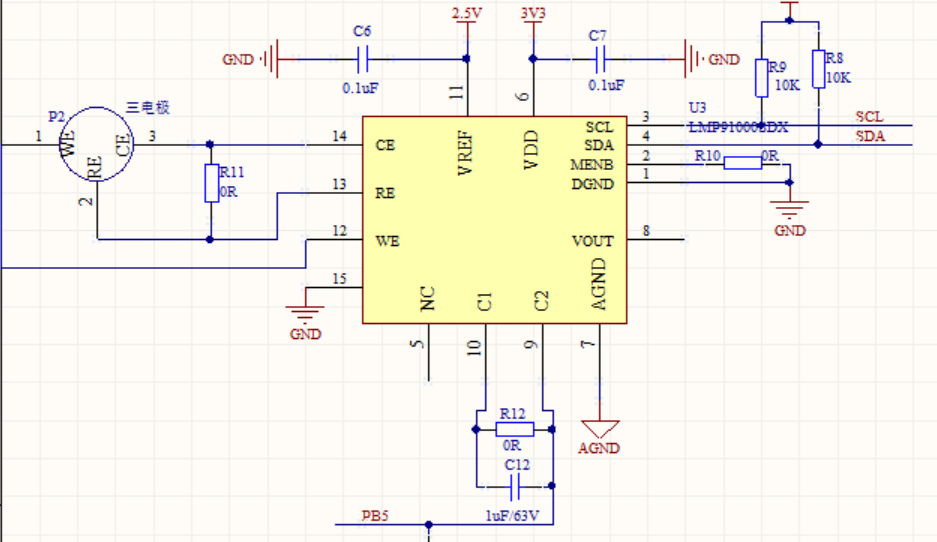
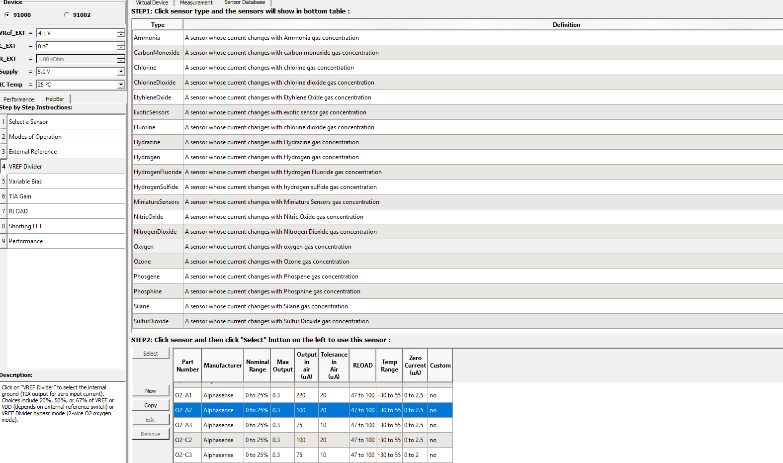
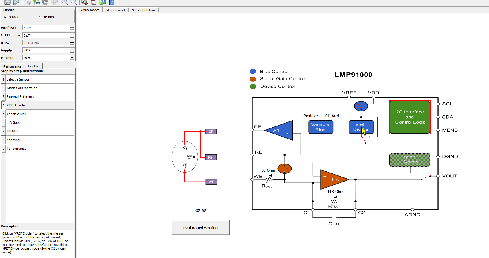
Customer used LMP91000 to do a project to measure gas concentration. He downloaded the code based on MSP430 microcontroller on the Internet. Set LMP91000 at the beginning of the program, the command was 0X48. 0X48 was the address of 91000. The customer wanted to know whether to write the address directly, can read data from 01--12 without writing any command? Then writed 0X00 and 0X18? Customer was unable to understand this well.

I2CSetup(LMP91000_I2C_Address);     (0X48                                      // Initialize I2C modul

TI_LMP91000_MENB_PxOUT &= ~TI_LMP91000_MENB_PIN;                                           // Enable \MENB Pin

TI_LMP91000_MENB_PxDIR |= TI_LMP91000_MENB_PIN;                                                 // Set pin direction is outpu

while (status == TI_LMP91000_NOT_READY)   (0X00)                                                     // wait while device is not ready

   status = LMP91000_I2CReadReg(TI_LMP91000_STATUS_REG);          (0X00)                     // Read device ready status

read_val[0] = LMP91000_I2CReadReg(TI_LMP91000_LOCK_REG);         (0X01)                // Read from lock register default value    

read_val[1] = LMP91000_I2CReadReg(TI_LMP91000_TIACN_REG);        (0X10)                // Read TIA control register default value  

read_val[2] = LMP91000_I2CReadReg(TI_LMP91000_REFCN_REG);         (0X11)                // Read Reference control register default value

read_val[3] = LMP91000_I2CReadReg(TI_LMP91000_MODECN_REG);   (0X12)               // Read Mode control register default value

                          (0X01)                       (0X00)

LMP91000_I2CWriteReg(TI_LMP91000_LOCK_REG, TI_LMP91000_WRITE_UNLOCK);       // unlock the registers for write

                           (0X10)                         (0X18)

LMP91000_I2CWriteReg(TI_LMP91000_TIACN_REG, TIACN_NEW_VALUE);                // Modify TIA control register

read_val[1] = LMP91000_I2CReadReg(TI_LMP91000_TIACN_REG);                   // Read to confirm register is modified

                          (0X10)

// test if write/read values match

if (read_val[1] == TIACN_NEW_VALUE)         (0X18)

{

   while (1)                                                                 // no error: blink LED continuously

   {

       __delay_cycles(250000);

       __delay_cycles(250000);

       TI_LMP91000_LED_PxOUT ^= TI_LMP91000_LED_PIN;      

   }

} else

{

   TI_LMP91000_LED_PxOUT &= ~TI_LMP91000_LED_PIN;                             // error: Set LED OFF  

}  

                               (0X10)                             (0X03)

LMP91000_I2CWriteReg(TI_LMP91000_TIACN_REG, TI_LMP91000_TIACN_REG_VALUE);   // store default value back in TIACN

                             (0X01)                            (0X00)

LMP91000_I2CWriteReg(TI_LMP91000_LOCK_REG, TI_LMP91000_WRITE_LOCK);         // lock the registers

TI_LMP91000_MENB_PxOUT |= TI_LMP91000_MENB_PIN;                             // Disable \MENB Pin 

Best Regards,

Annie 

  • Dear Annie - 

    (The registers 0x02 through 0x09 are reserved, so no point in reading them) 

    the procedure would be to (using the MENB as a chip select, or if just one device is being read here, MENB line can be tied low)

    1. read the status register first to see if the device is ready (this is optional)

    2. registers 0x10, 0x11 and 0x12 can be read out

    or

    2. register 0x01 can be written to, to unlock and then registers 0x10, 0x11 can be modified, for example: 

    unlocking and writing 3 registers (zoom out)

    unlocking operation over I2C (zoom in)

    Writing 0x10 with 0x0E (zoom in)

    Writing 0x11 with 0xC0 (zoom in)

    Writing 0x12 with 0x03 (zoom in)

    3. register 0x01 can be written to, to re-lock (if desired)

    Register 0x12 can be written to without unlocking operation described above.

    in the MSP430 code you refer to, there are 4 demo application examples  - please check them out before you modify. 


  • Hi Josh,

    Thanks. And customer has below following question need your help.

    1. He used LMP91000 to measure the gas concentration. He wrote commands to the LMP91000 through the IIC bus, and then sampled the VOUT terminal signal of the LMP91000 with the AD port of the single-chip microcomputer. Is that the concentration value? This was how he measured now, the measured data has been 0V. He did not add the electrode to measure, which is equivalent to LMP91000 no load.

    2. How to choose the resistance value of C1 terminal and C2 terminal of LMP91000? In the manual, C1 and C2 are indirectly connected with a 0 ohm resistor. But isn't C1 and C2 used to configure the transimpedance of TIA? If he connects a 0 ohm resistor, isn't the configured transimpedance impedance short-circuited?

    3. Is the customer's register setting correct?

    void LMP91000_INIT(void)
    {
    LMP91000_IO_INIT();
    i2c_Start();
    i2c_SendByte(0x48);
    i2c_SendByte(0x01);
    i2c_SendByte(0x00);
    i2c_Stop();
    i2c_Delay();
    i2c_Delay();

    i2c_Start();
    i2c_SendByte(0x48);
    i2c_SendByte(0x10);
    i2c_SendByte(0x0C);
    i2c_Stop();
    i2c_Delay();
    i2c_Delay();

    i2c_Start();
    i2c_SendByte(0x48);
    i2c_SendByte(0x11);
    i2c_SendByte(0xC0);
    i2c_Stop();
    i2c_Delay();
    i2c_Delay();

    i2c_Start();
    i2c_SendByte(0x48);
    i2c_SendByte(0x01);
    i2c_SendByte(0x01);
    i2c_Stop();
    i2c_Delay();
    i2c_Delay();

    i2c_Start();
    i2c_SendByte(0x48);
    i2c_SendByte(0x12);
    i2c_SendByte(0x03);
    i2c_Stop();
    i2c_Delay();
    i2c_Delay();
    }

    Annie

  • Dear Annie - 

    The TIA resistor gain is either internally set (with register 0x10, values 001b to 111b, for bits 4:2, in that register) or the register 0x10 is set to external (using same bits and set to 000b) and the gain setting is done with external resistor - it is not (and is not shown or described) as being shorted or zero Ohms.

    The sensor example settings (as the specific sensor is not mentioned yet by you) can be found by using the EVM tool (even if you (or the customer) don't have the EVM, which I would recommend getting) - 

    https://www.ti.com/lit/zip/snac007 (this is the software)

    https://www.ti.com/tool/LMP91000EVM (sensor board, which can connect directly to MCU, MSP430 source available on the product page, as you have already found, I think)  

    one can choose the sensor being used from the database and get the basic settings - here you can see example with O2 sensor

    choose sensor:

    then see settings