This thread has been locked.

If you have a related question, please click the "Ask a related question" button in the top right corner. The newly created question will be automatically linked to this question.

IWR6843: Sensor is not starting and capturing data when run Vital Sign Demo on IWR6843 based EVM

Part Number: IWR6843
Other Parts Discussed in Thread: MMWAVEICBOOST,

Hi,

I'm using IWR6843 based EVM and tried to run Vital Sign Demo from mmWave industrial toolbox 4.2.1. When I run the default demo GUI, it is detecting wrong ports automatically.

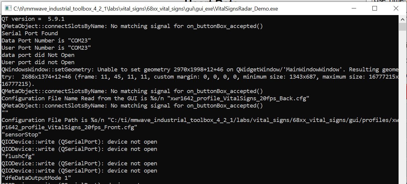
So I modified the GUI source code from automatic detection of ports to manual. It connected to the ports successfully but failed to capture the data.

As part of debugging,

1. I power cycled the board, reset the board - no difference.

2. Instead GUI, tried to capture data via tera term and threw errors ("Number of averaged chirps is not power of two ") in configuration command (calibDcRangeSig -1 0 0 0 0) and in mss_main.c. Attaching the snapshot of it.

 The "calibDcRangeSig -1 0 0 0 0" changed to "calibDcRangeSig -1 0 -5 8 256" by referring the SDK user guide and it sent successfully. But I don't know how this will effect the demo.

So can you please help me to get this resolved?

  • Hi Arun,

    It seems you are using the IWR6843AoPEVM, you will need to use this EVM with the MMWAVEICBOOST board for it to run the Vital Signs Lab.

    Please note that the Vital Signs Lab is provided as-is and support for it on E2E Forums is limited.

    Regards,

    AG

  • Hi Akash,

    I'm using IWR6843AOPCB not AoP EVM.

    Regards,

    Arun

  • Hi Akash,

    I'm using customized AoPCB board.

    Still debugging this issue. I found that there is no event received from BSS and failed to open mmwave module. But I didn't get the reason why it is failing.

    The Out-of-Box demo is working fine. Only Vitals Sign is failing. I used profile configuration from "mmwave_industrial_toolbox_4_2_1\labs\vital_signs\68xx_vital_signs\gui\profiles\xwr1642_profile_VitalSigns_20fps_Front.cfg"

    This board is having CP2105 usb-to-uart bridge.

    As part of debugging I tested the USB data line, UART data line, power and even tried by giving more power. Sill the output same.

    Testing the hardware as well.

    Can you please suggest some reasons why the communication between BSS is failing?

    Thanks

    Arun

  • Hi Arun,

    We are also facing same issue with custom board, Not sure why it only works with boost board. Please let us know if you got any luck to solve this issue. 

    Hi Akash,

    Please help us to solve this issue. 

  • Hi Chetan,

    We're using CP2105 USB-to-UART interface. This is the only difference we found from IWR6843ISK with MMWAVEIC BOOST board. And also we approached this problem in several ways which already addressed above.

    Have you done any debugging for this issue? If so please share information regarding that, which may help us to attack this issue.

    What USB-UART interfacing are you using in your board?

    Thanks

    Arun

  • Arun,

    The Vital Sign demo is only verified with SDK 3.3.Please use the same. 

    You should be able to verify the data coming on uart data port after sending the chirp config

    The GUI currently only supports UART port through MMWAVEICBOOST. You will need to modify the GUI to support the UART on your custom boards.

    Thanks

    Yogesh