This thread has been locked.

If you have a related question, please click the "Ask a related question" button in the top right corner. The newly created question will be automatically linked to this question.

LDC1000EVM: Determining the impedance of a material

Part Number: LDC1000EVM
Other Parts Discussed in Thread: LDC1001

I’m trying to find the impedance of a carbon fibre composite material with the LDC1000evm. Next to inductive and resistive properties, the material is likely to have capacitive properties. First I want to setup a correct measuring method while excluding the capacitive properties, which would work on for example a metal. After that I want to include the effect of the capacitive properties. To understand how to analyse the data I have used  the document‘LDC1000 Inductance to Digital Converter (Rev. A)’ I do, however, not fully understand how to determine the impedance and would greatly appreciate it if anyone could help me out. With the outputs of the sensor I see two possible methods to get to the impedance.

 I added page 9 of the document as an attachment.

1.With the proximity data.

In the documentation it is stated that Y=Proximity Data/2^15

If Y is the admittance the impedance can be calculated with Z = 1/Y

Questions I have about this:

Is Y actually the admittance? I can’t seem to find any documentation on the definition of Y.

What is the proximity data exactly? How is it determined? It implies that it is the proximity of a sample, however without knowing the properties of a sample can this be determined?


2. With Rp and the frequency

The impedance can also be solved for the circuit shown on Figure 10 (page 9), if the Rp, frequency, inductance and capacitance are known.

Question I have about this method:

With the impedance transformation that is performed to get Rp (page 9), what assumptions are made? It seems as if the frequency is assumed to be the natural frequency. Is this correct? And if so why can this be assumed, considering that the inductance L(d) is dependent on the sample?

Is this impedance transformation still valid considering that the capacitance is also dependent on the material when C is replaced by C(d)?

If possible, I would greatly appreciate it if anyone could provide a more elaborate derivation of the impedance transformation that is done to determine Rp.

 Any help would be greatly appriciated.

 impedance_transformation.pdf


  • Allard,

    Thank you for reaching out.  The LDC1000 has been replaced by LDC1001.  They operate in the same way, so I will refer to the newer device's datasheet.  

    The snippet from the datasheet above shows the equation you referenced for 'Y', but also includes the follow up bullet explaining Proximity data.  Here it described at the the output to represent the value of Rp.  However, 'Y' is typically representative of admittance as you mention.  Figure 10 in the datasheet aligns with this interpretation given the inverse relationship of the output code and the Rp value.

    The LDC device will track the resonant frequency of the system and will perform conversions at a sample rate (SR)  based on the programmed value for response time (register 0x04).  This information is used in the conversion process to determine Rp.

    You are also correct that some assumptions have been made.  Looking at the simplification we can see that there is no distance dependent Capacitance in the provided equations and other parasitic L/R/C values are not included.  Typically these should be negligible to the overall system, but certain design flaws in the coil can impact the overall result.  Please refer to the linked guides below for more information:

    LDC Sensor Design

    http://www.ti.com/lit/an/snoa930b/snoa930b.pdf

    Measuring Rp of a LDC Sensor

    http://www.ti.com/lit/an/snoa936/snoa936.pdf

    LDC target design

    http://www.ti.com/lit/an/snoa957a/snoa957a.pdf

    LDC E2E Guide

    https://e2e.ti.com/support/sensors/f/1023/t/295036

  • Allard,

    I received further clarification on 'Y'.  This variable represents the equivalent impedance of the total resonant circuit and target, but it is a unit-less number.  When you change L or C without changing the target response you should see a change in Y as well.  

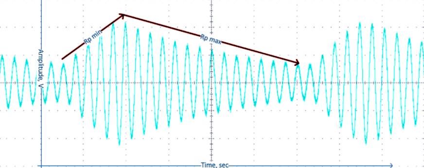
    The output signal on the tank can be observed as shown below

    The Rp measurement is done by driving two different levels of current until the sensor oscillation amplitudes reach maximum and minimum values. The proximity data is a ratio of the time to reach the maximum amplitude and the time to reach the minimum amplitude.  Considering the Rp equation discussed before, you can consider Y comparable to a duty cycle of the two current levels.

  • Hi Scott,

    Thank you for answering my questions. I am a mechanical engineering student, trying to make sense of electronics, so I greatly appreciate your help.

    I do however have some questions and hope you could help me.

    - First of all the text above equation 2 says the equation determines the impedance, while on the left side of the equation only Rp is present. Until now this has confused me because I assumed the inductance and capacitance would have some influence on the impedance. Then I started to wonder that maybe the impedance is equal to Rp because the Rp is determined for the resonance frequency, so the influence of the inductor and capacitor cancel eachother out. I figure that using Rp_MIN and Rp_MAX the sensor starts 'scanning' for the impedance at which resonance occurs, and then calculates values for this frequency. Is this correct or am I misinterpreting the system?

    Now I would like to compare two measurements using Rp, let's say a measurement close to the target (measurement 1) and one far from any conducting material (measurement 0). Considering that both values of Rp are measured at a different frequencies, they cannot simply be compared right? A proper comparison should compare the two impedances at the same frequency. Let's say we evaluate at f_0, than

    Z_0 = Rp_0

    And Z_1 should be calculated. This can be done with the inductance, capacitance (which both are frequency independent) and the Rp_1 at f_0. Yet the sensor only outputs Rp_1 at f_1, since this is iets resonance frequency. 

    So I am wondering if there is a way to read the Rp at different frequencies than the natural frequency. And also if my reasoning so far is correct.

    - Furthermore I am not completely clear on what the function of equation 2 is. The sensor outputs Rp directly, why would I want to calculate Rp using the range of Rp and Y?

  • Allard,

    The mutual inductance between the target and the sensor coil will definitely impact the impedance and therefore causes shifts in the resonant frequency. In the datasheet this added inductive effect is represented as L(d), which is a distance dependent portion of the equivalent inductance.

    Equation 2 allows you to convert the output proximity data to calculate Rp.  The actual digital output code will depend on the ranges for RP_MIN and RP_MAX. The device doesn't output Rp directly.

    In equation 2, RP_MIN and RP_MAX are input registers used to define the measurable range for Rp.  It is important to follow the guidelines in section 8.1.1 to determine where to set these. If set incorrectly it can cause the device to time out while attempting to find Rp.  The device  is using a comparison of the time it takes to reach the maximum and minimum values for the Rp calculation. 

    Please note the instructions regarding Equation 4.  These detail how you can calculate the changes in Inductance between your two measurement locations.

    How the Rp value translates to actual position will require calibration during the setup.  This is an important part of the process in determining the correct settings for RP_MIN and RP_MAX and requires you to use an impedance analyzer to find the values of Rp with your target in each location.

  • Scott,

    Thank you for your reply.

    I see now that the sensor does not output the Rp, sorry for the confusion. I am using the 'Sensing Solutions EVM GUI' and can directly stream Rp values, and thus assumed they were outputted by the sensor. But instead the sensor itself only measures the proximity data and the software calculates values such as Rp or L with given input values for Rp_MAX, Rp_MIN etc. Right?

    If I understand you correctly, you say that the only way to be able to compare two measurements at different frequencies is to calibrate with an impedance sensor?

    Or is it possible to choose the frequency at which the impedance of the LC resonator is measured? Or even perform a frequency sweep? 

    Kind regards,

    Allard

  • Allard,

    You are understanding correctly.  The device outputs the proximity data value which can be used to calculate Rp in the software based on the known settings for Rp Max and Rp Min.

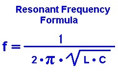
    The resonance of the LC tank is determined by the equation:

    The target will cause this resonant frequency to change slightly when the mutual inductance L(d) becomes significant enough.  As the target gets closer to the sensor, this change will become more dramatic and will result in changes to the time it takes to ramp the waveform on the LC tank.  This is used by the device to calculate the proximity data output.

    Performing a resonant frequency sweep of the would require manually changing out either the L or C component to adjust the frequency of the sensor.  Please note and follow guidance in section 8.1.3 of the datasheet.  Also, Section 8.2 discusses a typical application with an example setup procedure.

  • Hi Scott,

    Thank you for your reply.

    A I understand it now, in order to achieve my goal, I will have to do some further research. Nevertheless your explanaition has been very helpfull. Thanks!

    Allard

  • Allard,

    I'm glad I could help.  If you have no further questions, please go ahead an mark the thread resolved.

    Thanks,

    Scott