This thread has been locked.

If you have a related question, please click the "Ask a related question" button in the top right corner. The newly created question will be automatically linked to this question.

LDC1612: Question for LDC1612

Part Number: LDC1612

Hi Team,

The customer is experiencing below issue and needs your help.

He uses LDC1612, and the drawing used is the reference board of TI. He fixed the distance between the test object and the LDC1612 coil, and placed it in a high and low temperature box for cyclic testing. An output value we measured at room temperature is stable, then after the system has passed a high temperature of 80 degrees for a few hours, then reduce the temperature to room temperature. After stabilizing at room temperature for a sufficient time, he found that the stable output value afterwards had more than 100 drift changes before high-temperature baking. He has done the above experiments with both internal and external crystals, and found that there is a large deviation (at a distance of 9mm, the reading drifts by more than 100).

He would like to know is it caused by LDC1612 or other reasons? 

The key 330pF capacitor he used NP0 high stability capacitor. He hopes that the system will repeat the cycle from -40 degrees to 80 degrees. Under the same test object, test distance, and the same temperature, the test readings will be consistent. Can this goal be achieved?

Thanks,

Annie

  • Hi Annie,

    Can you clarify a few things for me?

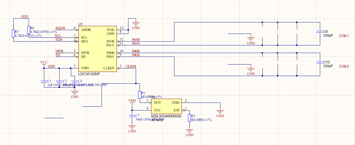
    • Is the customer using the default LDC1612EVM, or have they just used the coil from the EVM and connected it to another board? If they are using a different board, can you share the LDC section of the schematics and how the sensor is connected to the board?
    • Is the drift measured in output codes? So a drift of 100 means 100 output codes?
    • Did the customer measure any differences when using the internal vs external oscillator?

    Please note that the sensor inductance will change slightly over temperature due to thermal expansion, so it's not possible to maintain the exact same output code across the full temperature range. Any change in the sensor capacitance or the reference frequency will make this change larger.

    Best Regards,

  • Hi Kristin,

    Customer provided the feedback just now.

    1. The customer used LDC1612EVM, similar test results he saw. That is, when the temperature returns to the original temperature, there is a drift, and the raw data thousand-digit reading changes. They are further testing to verify whether this is the case. Before his test was on his own board, the sensor coil and circuit are the same as EVM. 

    2. A drift of 100 means that the readings of DATA_MSB_CH1 and DATA_LSB_CH1 have a change of more than 10,000. 

    data_buff[i] = LDC1612_ReadInt(DATA_MSB_CH1);
    data_buff[i] = (data_buff[i] << 16)&0x0fff0000;
    data_buff[i] |= LDC1612_ReadInt(DATA_LSB_CH1);

    3. He knows that at the same test distance, there will be changes due to different temperature readings. But the problem he encountered was that the reading at a certain temperature and a certain distance, after returning to the original temperature after a high temperature, found that the reading drifted by more than 10,000. In other words, he measured a value at 27 degrees and a distance of 7mm. Then the incubator heats up to 80 degrees, stays at 80 degrees for an hour, and then cools down to 27 degrees. At this time, the reading has a large drift from the initial reading at 27 degrees. This drift is even greater than the change in reading caused by the change in distance between 7mm and 8mm. Therefore, this drift is too large to be practically applicable. His test method is based on the traditional eddy current sensor usage, that is, the coil plane is parallel to the measured surface, and the change in distance will change the reading.

    Thanks,

    Annie

  • The coil uses the on-board coil like EVM.

  • Hi Annie,

    Thanks for the clarifications and the additional information. I have a few more questions:

    • When the customer returns the board to 27 degrees, how long does he keep the board at this temperature before reading the LDC output data? If he keeps the board at this temperature for a very long time, does the output data ever return to the initial value?
    • What does the value read when he power cycles the device after the temperature testing?
    • Is the customer changing the drive current settings at all?

    It would also be helpful to see oscilloscope screenshots of the INxA/INxB pins to make sure that the sensor oscillation amplitude is within the recommended range.

    Best Regards,