This thread has been locked.

If you have a related question, please click the "Ask a related question" button in the top right corner. The newly created question will be automatically linked to this question.

LDC1101EVM: LDC1101 register configuration

Part Number: LDC1101EVM
Other Parts Discussed in Thread: LDC1101

Hi Experts,

I'm new to sensors like LDC1101(metal detection), I just want to ask

1) what is Rp+L mode? what does Rp indicates here?

2) For using Rp+L mode do we need to do any register configuration?

3) I want to detect metal thickness using LDC1101, so will I be able to measure thickness of a metal using LDC1101?

Sorry for my questions, as I'm asking I'm new here. Please guide me with giving me some of your valuable information. I will be grateful for that.

  • Hi Manish,

    For your first question, I recommend looking at our LDC E2E FAQ, linked in my signature below. The application note LDC Sensor Design within the FAQ should answer your questions.

    If you use Rp+L mode you will need to configure several registers. I recommend reading sections 8.4 and 9.2 of the datasheet for more information about how to configure the device.

    The LDC devices do not measure metal thickness directly, but you may be able to use them to measure a limited range of metal thicknesses. Because of the skin effect, the eddy currents that form on the target metal flow close to the surface. The higher the sensor frequency, the closer the more current is concentrated at the surface of the target. If a target is not thick enough to support >95% of the possible eddy currents, you will see a reduced inductive response. You may be able to indirectly measure the metal thickness by measuring the strength of the inductive response. However, this method would be very sensitive to the distance between the target and the sensor coil. Very small changes in the target distance can cause significant changes in the sensor inductance. This is how most customers use inductive sensing, but in your application would be a significant source of error. You'd also have to make sure that the target material was consistent, because changes in target conductivity will also change the inductive response. LDC Sensor Design should enhance your understanding of this. We also have a skin depth tool in the LDC Tools excel calculator, also found in the FAQ.

    Best Regards,

  • Hi Kristin,

    There are almost more than 30 registers for configuring Rp+L mode? Actually this is very new topic for me can you describe me about which registers shall I configure? Please.......

  • Hi Manish,

    Section 9.2.2.1 of the datasheet describes in detail which registers to configure for Rp + L mode with an example sensor. There are only 5 registers that need to be configured. Table 40 summarizes the registers and the specific register fields that were discussed in section 9.2.2.1.

    If you are new to inductive sensing, I really recommend reading through the FAQ before trying to configure the register settings. It should help your understanding.

    Best Regards,

  • Hi Kristin,

    Thanks for the detailed information after going through all FAQ and register configuration table even if I face some issue regarding to my understanding I'll post it here. Meanwhie, I request you not to close this thread. Please

  • Hi Manish,

    Whenever you reply to an E2E thread, it reopens the thread and notifies us that someone has replied. If a thread is inactive for a long period of time it will lock, but you can always post a new thread if you have additional questions. You can also click the "ask a related question" button if you have further questions about the same topic that a locked thread discussed.

    Best Regards,

  • Hi,

    Got it. Thanks.

  • Hi Kristin,

    How we can increase its effective resolution. Can you say that?

    I was going through this link but I could not get. Can we increase its effective resolution?

  • Hi Manish,

    Can you explain which parts of the application note were unclear to you? 

    These are the main ways to improve resolution:

    • Maximize the inductive target's response
      • Use a highly conductive target at least three skin depths thick
      • Minimize the distance between the target and the sensor coil
      • Size the target at least as large as the sensor coil
    • Use a reference oscillator with the maximum frequency that the LDC device supports
      • Also minimize the oscillator's jitter and drift over temperature
    • Use the slowest possible sample rate

    Best Regards,

  • Hi Kristin,
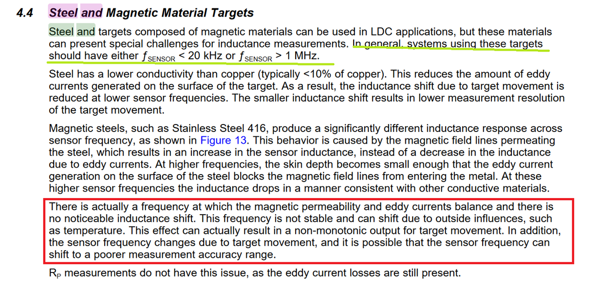
    Kindly check the attached image there I have marked several points.

    metal which I'm testing is stainless steel so, the area which I have marked as green marker. Can you say that do we need to set minimum frequency there?

    And the area which I have marked as red there it is saying that frequency is not stable and shift can happen due to outside influences such as temperature. So is this condition is apllied to only steel? please clear me those statements. I'm very much confuseed here. Its a kind request.

  • Hi Manish,

    My apologies for the very delayed reply. I have actually switched to a new group and am no longer supporting the LDC devices. I'm happy to answer your question, but if you have follow-up questions please post a new thread for the current LDC engineers to support.

    This condition is possible for ferrous metals like steel and iron. It will not occur with non-ferrous metals like copper or aluminum. Ferrous metals are permeable, and at low sensor frequencies the presence of a ferrous metal target will actually cause the sensor frequency to increase. At high frequencies, the eddy currents dominate the response, so the sensor frequency will decrease. The above section notes that at some frequency it is possible for the magnetic permeability and eddy current responses to balance, so the sensor frequency will not shift, even though there is a target present. If you keep the LC tank sensor under 20kHz you will only see permeability effect, and above 1MHz you will only see an eddy current effect. The LDC1101 doesn't support sensor frequencies lower then 500kHz, so if you operate above 1MHs you shouldn't have any issues with this phenomenon.

    Best Regards,

  • Hey Kristin,

    Got it thanks for your above reply. It is quiet helpful for me.