This thread has been locked.

If you have a related question, please click the "Ask a related question" button in the top right corner. The newly created question will be automatically linked to this question.

PGA305: read EEPROM register

Part Number: PGA305
Other Parts Discussed in Thread: PGA300

Hi,

I am trying to read via I2C some register but I can't understand why, probably because I transmit the wrong address.

For example, I wish to read:

PADC_GAIN_MSB with DI page and offset = NA and address 0x40000046

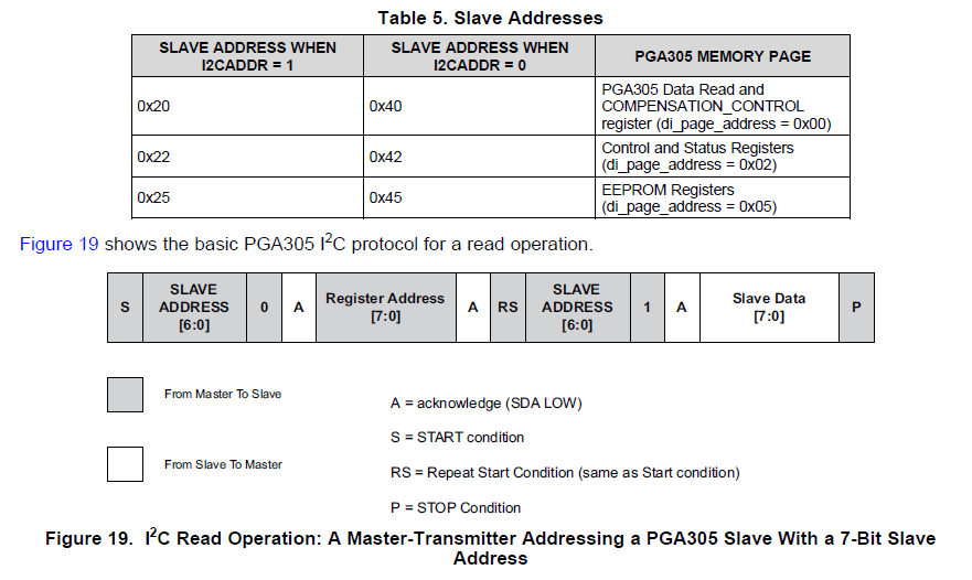
I2CADDR = 0 so the slave address is 0x40.

So I have to trasmit the slave address (0x40) the register address (0x46) then again the slave address, is it correct?

If DI Page is not NA i have to sum the slave address?

if DI Offset is not NA?

Thank you in advance.

  • Hello Andrea,

    The EEPROM space is actually part of a different slave address. If I2C_ADDR = 0, then you access the EEPROM for reads by using the slave address 0x45:

    For a read directly from the EEPROM, you will just use the EEPROM address shown in the register map 0x46. Note that even though Table 20 shows the PADC_GAIN_MSB as a "Control and Status Register" since it has an EEPROM address, you will access it by using the EEPROM register slave address.

    Regards,

  • ok, as I just read all the register listed in table 20, i can use for all of them 0x46 as slave address and the proper register map as register address? Even those register who have DI Page and DI offset?

    My final purpose is to copy on my MCU almost all of the register listed in table 20.

  • So I can read the register directly from the EEPROM using:

    • slave address 0x45
    • register address: the last two bytes of the EEPROM addres listed in table 20

    Do I need to write the page i would like to read in the EEPROM_PAGE_ADDRESS before doing that?
    How can i read the register without the EEPROM addres of table 20? Should I use the DI Offset? DI offset shoud be interpreted like the offset from 0x40 00 00 00?

    Thank you

  • Only the EEPROM registers can be read using slave address 0x45.

    To write to the EEPROM, you have to use the EEPROM cache. Please refer to the "EEPROM Programming Procedure" section of the datasheet. There are 16 pages of 8 bytes each, and you can write a single page with the contents of the EEPROM cache. The page of a specific register is determined by using the last byte of the EEPROM address and counting up from 0x0. So 0x0 through 0x07 will be on page 0, 0x08 - 0x0F will be on page 1, etc.

    If the register is also available outside of the EEPROM, you can use the DI offset while using slave address 0x40.

    Regards,

  • Ok, the writing process was ok, now the reading is almost fine. I can't read the EEPROM_CRC_VALUE, i use 0x45 as slave address and as EEPROM ADDRESS 0x7F but it always return Zero, even after trying to writedifferent values into EEPROM.

    Thank you for your support, is very precious.

  • Hi Andrea,

    It's a little bit confusing, but there are actually 2 EEPROM_CRC_VALUE registers. The last byte of the EEPROM itself is 0x7F, and this is where you will write your EEPROM_CRC_VALUE after it has been calculated. The other register is 0x8D (on the same memory page/slave address), and this is where the calculated CRC is available.

    Once you have programmed the EEPROM the way you want it, set the CALCULATE_CRC bit in the EEPROM_CRC register (0x45 slave address, register 0x8A, data 0x01). This will initiate the calculation and place the calculated CRC value in 0x8D. You can read the calculated value there, then use that same value and program it into 0x7F of the EEPROM using the EEPROM cache.

    When the compensation engine is running, it will compare the value in 0x7F to the calculated value in 0x8D, and if they don't match it will cause an error as described in the EEPROM CRC section of the datatsheet.

    Regards,

  • Hi Scott,

    I'm here again, I'm having some problem with I2C that delayed my last question.
    The CRC placed in the register 0x8D is calculated from PGA if I set the CALCULATE_CRC_bit and is calculated every time I write any page of the EEPROM (page 36) even if I don't set the CALCULATE_CRC_bit?
    In the second case I need to wirte the new CRC every time I wrote a page, correct?

    Last thing, for reading the CRC calculated from PGA I just need to set 0x42 as slave address and 0x8D ad register address correct? I can't test it due to my I2C issue..

    I'm confused because I haven't understood the difference between offset address and eeprom address. EEPROM_CRC_VALUE and a few have both.

    Thank you very much, after that i think all my issue can be considered solved.

  • I've read some device had issues.

    The marking on my PGA is:

    PGA305A

    RHH

    TI 96I

    A5GV G4

  • Hello Andrea,

    There should not be any problem with the I2C on this part. What issue are you seeing? 

    Yes you will need to write a new CRC value in the last byte of the EEPROM any time you change any register in the EEPROM. The calculated EEPROM CRC value is actually still on the same interface page as the EEPROM, so you will write to slave address 0x45 and read register 0x8D.

    Some EEPROM registers have the same function as some of the control and status registers. When you set it in EEPROM it will set that control and status register to the saved EEPROM value every time you power on the PGA305. That is why there is an offset (used to access the control and status register) and an EEPROM address (used to read and write to the EEPROM).

    We are in the process of updating the PGA305 datasheet to make this more clear. The PGA300 is a very similar device, and has an updated datasheet that explains the register map in a more coherent way. I recommend checking the PGA300 datasheet to see how the EEPROM registers are different from the control and status registers.

    Regards,

  • Scott Cummins said:
    There should not be any problem with the I2C on this part. What issue are you seeing? 

    I'am having problems reading the register, unfortunatly we use a uC with any I2C port so we emulated it with PWM. I try to debug with an oscilloscope and it seems fine. Sometimes I successfully read the register some other no.

    Anyway really thanks for your support so far.

    Regards

  • Hi Andrea,

    Are you placing the device in reset mode before attempting to read and write registers? You will need to write 0x03 to register 0x0C (slave address 0x40) to put the PGA305 in reset and then you can properly read and write all the registers.

    If you are already doing that, it is likely some kind of I2C timing error from the master. You can post some examples of I2C transactions that are unsuccessful and I will take a look. Include SDA, SCL, and CS in the scope captures.


    Regards,

  • Yes, i put the PGA in the Reset mode. It reads casually some registers and usually different, not always the same.


    Here the register 0x35, it should read 132 (decimal). The second picture read 0x54 and sould read 0x12


  • In the upper post you will see that the receive byte has 9 bit instead of 8. In this way it works wometimes.
    I tried to modify for receiving 8 byte as the I2C protocol say but in that version it never read. i post a screen for this too.

  • Hi Scott,

    I solved my issue. I tell you how as it can help:

    • I manage the CS making a read after every write of SDA and SCL.
    • I removed every delay inserted after every write of SDA or SCL, the transmission was probably too slow.
    • I add a control after every read, when I read all the register at the beginning sometimes it skips some register after an error. 

    Thank you again for you support.

    Bye