This thread has been locked.

If you have a related question, please click the "Ask a related question" button in the top right corner. The newly created question will be automatically linked to this question.

TPS8804: TPS8804 Questions

Part Number: TPS8804

Hello,

I want to use TPS8804 , but I need some informations about this IC(TPS8804).

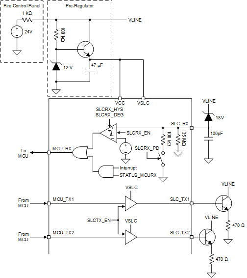
  • Firstly,How should I use SCL_TX1 and SCL_TX2? I know Digital Addressable Lighting Interface(DALI), but did not understand why there are two transmit pin?
  • In the datasheet: "The SLC_TX1 output driver is able to pull the line completely low" I think in this case, VLINE and ground will be shorted, am i thinking wrong?
  • Can you explain SLC little bit? I just know DALI and SLC are similar.

Thanks.

  • Hi,

    1. The TPS8804 SLC interface is designed to connect the MCU to the SLC power line. The SLC_TX1 and SLC_TX2 outputs modulate the voltage or current on the power line, allowing other devices to detect the change in voltage or current. Depending on how the protocol is implemented, SLC_TX1 and SLC_TX2 is configured as a voltage pull-down or current pull-down. The reason for two outputs is for multi-level communication or power loops where multiple transmitters are required.
    2. The SLC_TX1 output driver, when coupled to an external transistor, can pull the SLC power line to GND to transmit a signal. This is one example of the SLC communication.

    I am not familiar with DALI. I did read that DALI uses the same wires for power and communication, which is true with SLC. However, there is no standard voltage or current level protocol with SLC. This is why the TPS8804 does not have any specific applications or waveforms with SLC.

    Here is a similar question about SLC that provides more information: https://e2e.ti.com/support/sensors/f/1023/t/898132

    Let me know if you have any further questions.

    Best,

    Grant

  • Hello again,

    • Could you explain differences between SLC and DALI?.I did not find any schematic about SLC.

              I dont want detailed schematic, just want to know differences.For example should I use current limiter circuit for voltage pull-down or current pull-down?

    • I dont know that do I have to use SLC_TX1 and SLC_TX2 at the same time, because I did find any schematic about SLC interface.
    • In datasheet there are two connections about SLC_TX1 pin. Which one should I use in which case?

  • Hi,

    My understanding of the DALI interface is that there are standard voltage levels and timings to transmit standard commands to the connected devices. This is not true with SLC. While both systems are addressable, there is no standard protocol for SLC. To quote the other E2E question:

    "We don’t have SLC reference designs because each manufacturer has their own protocol.  This is intentional as the commercial detectors are mandated to be certified to only work with a particular fire panel or set of fire panels.  Because of this liability, the panel manufacturers keep the protocol and implementation proprietary so that they can guarantee that only the detectors and appliances they have control over can operate with their panel."

    A current limiter in the fire alarm control panel is a good idea if using voltage modulation to transmit data from the alarm to the control panel. But I cannot specify whether you should use it because I don't know the requirements of your system. I recommend reviewing the UL268 and UL864 standards to understand what the SLC communication needs to accomplish. Please note that I am not an expert on these standards.

    Using both SLC_TX transmitters may not be required for communication. The external components connected to SLC_TX1 depend on whether voltage or current modulation is used. In general, a system can use any combination of voltage or current modulation and voltage or current sensing. The configuration with SLC_TX1 below pulls down VLINE for voltage modulation. The configuration with SLC_TX2 does a voltage-limited current modulation that can be used with voltage or current sensing. I recommend installing a 4.7 kΩ resistor between SLC_TX2 and the NPN base to limit the SLC_TX2 current when using this configuration.

    You can see example schematics and waveforms below. Only one SLC_TX transmitter is used to modulate VLINE.

    Note that if you are trying to attach pictures in your posts, I cannot see them.

    Let me know if you have any further questions.

    Best,

    Grant