

TI Team,
Is there any known issue with the TMP392 having a 1-2ms "blip" on it's output upon being powered up?
This sensor shuts down our converter directly after start-up, and it seems that for some reason, even at cold start, there is this small event where the output is pulled low for a brief moment. There is a lot going on during this instance of time, but I looked and the event does not seem to correspond with any other switching event in the power supply- the boost PFC is already up and switching, the power supply which powers the TMP392 and the output pull-ups is already up- so it does not appear to be "induced" but rather just something that the part does on it's own.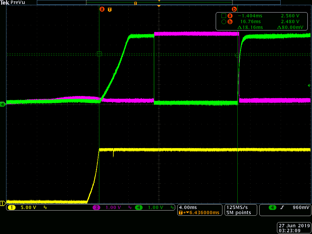
Thanks in advance for your help,
Cody

-
Ask a related question
What is a related question?A related question is a question created from another question. When the related question is created, it will be automatically linked to the original question.


