This thread has been locked.

If you have a related question, please click the "Ask a related question" button in the top right corner. The newly created question will be automatically linked to this question.

PGA460-Q1: Faill to store the setting into EEPROM

Part Number: PGA460-Q1
Other Parts Discussed in Thread: PGA460, ENERGIA, PGA460PSM-EVM, BOOSTXL-PGA460, MSP430F5529

Hi,

My customer feedback that they have problem on store the EEPOM setting, EEPOM cannot save the setting (even GUI or COM UART).

Any practice and datasheet can use as a reference to better understand the EEPOM store  procedure. thanks.

  • Hi Yue,

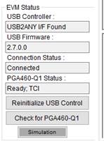
    When using the PGA460-Q1 EVM GUI to burn and program the EEPROM, do they go to the "Test Modes" page, and click the "Program EERPOM" button? Are they supplying VPWR with 6-28V?

    Note, the threshold time and level values are part of SRAM, not EEPROM, so if they are expecting to save the threshold values, it is not possible.

  • Hi Akeem,

    As we used the OWI mode for communication. So we did the EERPOM program in the interface "external IO pin only" and supply VPWR with 12V.

    I would like to modify some parameter like TVGAINx and PULSE_P1 in "pga460_ussc.cpp" file and store to form factory PCBA. Would you please advise the step procedure.

  • Hi Akeem,

    As we used OWI mode for communication, we did the EEPOM program in the “External IOpin only” interface. The VPWR was supplied with 12VDC.

    I would like to modify some parameter like TVGAINx and PULSE_P1 in "pga460_ussc.cpp" file and store to form factory PCBA. Would you please advise the step procedure.


    Thanks,

    leo

  • Hi Leo,

    Note, the IO pin offers two different One Wire Interface (OWI) modes: Time Command Interface (TCI) and One-Wire UART (OWU). These are two very different OWI modes, which is why it's important to know which you are using in the GUI to ensure you are using the correct OWI mode in Energia (TCI or OWU). By default, the GUI may switch between these two modes (unless specified to operate in one exclusive mode), while the Energia sketch can only currently be used in one OWI mode.

    The general procedure of updating, programming, and burning the EEPROM memory is:

    1. Send bulk register write command (command 12) or several singe register write commands (command 10) to update the device settings. See Energia functions pga460::defaultPGA460 (bulk write) pga460::registerWrite (single write) in PGA460_USSC.cpp file for an example implementation.
    2. Execute EEPROM burn routine as described in section "7.6.1 EEPROM Programming" of the datasheet. See Energia function pga460::burnEEPROM in PGA460_USSC.cpp file for an example implementation.
  • Hi Akeem,
     
    Reply 1 : Please see below that the EVM status in GUI and Energia Sketch shall selected the TCI mode.
     
    Refering separate email :
    The retrieving echo data dump profile saturated and no object be detected. Is my command set correct?
    [BU]The echo data dump did not appear to actually be captured since all values are 255. Is the customer using the TCI or OWU interface in the GUI? They have selected TCI in the Energia sketch.
    Reply 2 : See above reply1 that I used TCI mode for both GUI and Energia sketch.
     
     
    I’ve tried many time in Engergia sketch to burn the user EEPOM but it still not success and the echo data dump profile still saturated and no object detected.
    I have attach the result of COM port communication and the PGA460_USSC.ccp file (GetDistance.ino and PGA_460.h file are original TI code and change) . Would  you review attach and share more detail/procedure what shall I do on the EEPOM program and echo data dump setting.
     
    Thanks,
    Leo
     
  • Hi Leo,

    If you can send me your register memory map output text file from the GUI, I will use your exact register configuration to debug why the Energia sketch is not properly working for you. Are you able to monitor the PGA460 IO pin during the execution of the Energia sketch to see if there is any TCI activity? The issue is likely occurring due to one of the following steps:

    1. The master controller is not generating the TCI commands from Energia.
    2. The PGA460 is not responding to the TCI commands.
    3. The PGA460's IO interface is disabled or in OWU mode in its register configuration.
    4. The master controller is not collecting the TCI data from the PGA460
    5. The Energia sketch is not properly converting and reporting the master controller's captured TCI data.

  • Hi Akeem,
     
    I did successes the EEPROM programming by UART communication with our form factory module (anyway, I will take this for temporary used and keep study the EEPROM program by TCI mode.)
    Although the EEPROM can program but the result of system diagnostics, echo data dump profile and the object measure are very unstable. See below data.
    I’d tried to modify the FREQ_DIAG to value 0x15h (Diag. period = 3, Diag. start time=500us) from PGA460_USSC.ccp file. But the result is no change.  
    (I also try the PGA460PSM-EVM board, but the result is the same. Maybe the board was reset by me!)
     
    Query :

    1.       Do still need send you the register memory map output text file from the GUI for debug?

    2.       Our form factory PCBA circuit is most similar as PGA460PSM-EVM. Do you need send my circuit for check?

    3.       Do it need send you the .cpp and .ino file to check?

     
    Communication : UART
    Communication : TCI
    Command Set : 0510211111110
    Command Set : 1510211111110
    PGA460-Q1 EVM UART/TCI/OWU/SPI Energia Demo for Ultrasonic Time-of-Flight
    -------------------------------------------------------------------------
    Instructions: Configure the EVM by entering a byte value between 0-9 or 'x' per request.
    --- Input can be entered as a single string to auto-increment/fill each request. E.g. 0011211000510
    --- To skip the COM setup at any point, and use the hard-coded values from thereon, enter a value of 's'.
    --- To reset the program, and re-prompt for user input, enter a value of 'q'.
    --- To pause/resume the program when running, enter a value of 'p'.
    1. Communication Mode: 0=UART, 1=TCI, 2=OneWireUART, 3=SPI ... 0
    2. UART kBaud: 0=9.6, 1=19.2, 2=38.4, 3=57.6, 4=74.8, 5=115.2 ... 5
    3. P1 and P2 Thresholds: 0=%25, 1=50%, or 2=75% of max ... 1
    4. Transducer Settings: 0=Murata MA58MF14-7N, 1=Murata MA40H1S-R, x=Skip ... 0
    5. TVG Range: 0=32-64dB, 1=46-78dB, 2=52-84dB, or 3=58-90dB, x=Skip ... 72
    6. Fixed TVG Level: 0=%25, 1=50%, or 2=75% of max, x=Skip ... 72
    7. Minimum Distance = 0.1m * BYTE ... 1
    8. Run System Diagnostics?: 0=No, 1=Yes ... 1
    9. Echo Data Dump: 0=None, 1=P1BL, 2=P2BL, 3=P1LO, 4=P2LO,... 1
    10. Burn/Save User EEPROM?: 0=No, 1=Yes ... 1
    11. Command Cycle Delay: 100ms * BYTE ... 1
    12. Number of Objects to Detect (1-8) = BYTE ... 1
    13. USART Address of PGA460 (0-7) = BYTE ... 0
    Configuring the PGA460 with the selected settings. Wait...
    System Diagnostics - Frequency (kHz): 9.09
    System Diagnostics - Decay Period (us): 2016.00
    System Diagnostics - Die Temperature (C): 107.33
    System Diagnostics - Noise Level: 148.00
    EEPROM programmed successfully.
    Retrieving echo data dump profile. Wait...
    ,132,196,231,192,16,217,250,255,255,255,255,242,59,190,158,246,255,247,243,191,247,255,255,247,255,255,247,
    247,119,251,247,255,247,247,247,127,0,3,64,47,96,100,63,27,98,70,42,193,29,140,222,38,253,103,50,155,3,251,152,
    228,16,32,206,245,90,202,112,167,39,121,146,255,129,142,87,251,83,126,54,75,26,187,77,103,73,24,12,180,18,80,
    212,79,62,38,40,183,2,239,75,97,24,78,174,25,32,70,26,149,107,237,254,255,254,255,255,255,191,99,255,255,255,
    254,145,255,156,180,136,132
     
    P1 Obj1 Distance (m): 10.40
    P1 Obj1 Distance (m): 2.81
    P2 Obj1 Distance (m): 0.73
    P2 Obj1 Distance (m): 9.99
    P1 Obj1 Distance (m): 9.04
    P2 Obj1 Distance (m): 5.83
    P1 Obj1 Distance (m): 10.16
    PGA460-Q1 EVM UART/TCI/OWU/SPI Energia Demo for Ultrasonic Time-of-Flight
    -------------------------------------------------------------------------
    Instructions: Configure the EVM by entering a byte value between 0-9 or 'x' per request.
    --- Input can be entered as a single string to auto-increment/fill each request. E.g. 0011211000510
    --- To skip the COM setup at any point, and use the hard-coded values from thereon, enter a value of 's'.
    --- To reset the program, and re-prompt for user input, enter a value of 'q'.
    --- To pause/resume the program when running, enter a value of 'p'.
    1. Communication Mode: 0=UART, 1=TCI, 2=OneWireUART, 3=SPI ... 1
    2. UART kBaud: 0=9.6, 1=19.2, 2=38.4, 3=57.6, 4=74.8, 5=115.2 ... 5
    3. P1 and P2 Thresholds: 0=%25, 1=50%, or 2=75% of max ... 1
    4. Transducer Settings: 0=Murata MA58MF14-7N, 1=Murata MA40H1S-R, x=Skip ... 0
    5. TVG Range: 0=32-64dB, 1=46-78dB, 2=52-84dB, or 3=58-90dB, x=Skip ... 2
    6. Fixed TVG Level: 0=%25, 1=50%, or 2=75% of max, x=Skip ... 1
    7. Minimum Distance = 0.1m * BYTE ... 1
    8. Run System Diagnostics?: 0=No, 1=Yes ... 1
    9. Echo Data Dump: 0=None, 1=P1BL, 2=P2BL, 3=P1LO, 4=P2LO,... 1
    10. Burn/Save User EEPROM?: 0=No, 1=Yes ... 1
    11. Command Cycle Delay: 100ms * BYTE ... 1
    12. Number of Objects to Detect (1-8) = BYTE ... 1
    13. USART Address of PGA460 (0-7) = BYTE ... 0
    Configuring the PGA460 with the selected settings. Wait...
    System Diagnostics - Frequency (kHz): 7.84
    System Diagnostics - Decay Period (us): 4080.00
    System Diagnostics - Die Temperature (C): 127.33
    System Diagnostics - Noise Level: 255.00
    EEPROM program failed.
    Retrieving echo data dump profile. Wait...
    ,255,255,255,255,255,255,255,255,255,255,255,255,255,255,255,255,255,255,255,255,255,255,255,255,255,255,255,
    255,255,255,255,255,255,255,255,255,255,255,255,255,255,255,255,255,255,255,255,255,255,255,255,255,255,255,
    255,255,255,255,255,255,255,255,255,255,255,255,255,255,255,255,255,255,255,255,255,255,255,255,255,255,255,
    255,255,255,255,255,255,255,255,255,255,255,255,255,255,255,255,255,255,255,255,255,255,255,255,255,255,255,
    255,255,255,255,255,255,255,255,255,255,255,255,255,255,255,255,255,255,255,0
     
    No object...
    No object...
    No object...
    No object...
    No object...
    No object...
     
    Thanks,
    Leo
     
  • Hi Leo,

    I double checked the PGA460 Energia library to make sure the TCI mode is working properly. I was able to successfully perform everything except the EEPROM program routine when using TCI. During debug, I found an mistake in the PGA460_USSC.cpp file in the burnEEPROM function that is preventing the TCI mode EEPROM burn routine from running. There is only one line of code you'll need to manually update as highlighted below in the PGA460_USSC.cpp file:

    PGA460_USSC.cpp mistake in red PGA460_USSC.cpp correction in blue

    bool pga460::burnEEPROM()
    {
    byte burnStat = 0;
    byte temp = 0;
    bool burnSuccess = false;

    if (comm != 1 || comm != 3)

    bool pga460::burnEEPROM()
    {
    byte burnStat = 0;
    byte temp = 0;
    bool burnSuccess = false;

    if (comm != 1)

    I will update this in the next Energia revision release since this mistake is preventing both TCI and SPI from entering their EEPROM burn routines.

    Regarding your other TCI issues, try to following debug techniques:

    1. The master controller is not generating the TCI commands from Energia.
      1. Use an oscilloscope to probe the BOOSTXL-PGA460's TCITX and TCIRX pins, and the PGA460PSM-EVMs IO pin. By monitoring these pins, and simply checking for toggle activity, we will confirm whether the master controller is actually generating the TCI commands from Energia in the first place.
    2. The PGA460 is not responding to the TCI commands.
      1. Use an oscilloscope to probe the BOOSTXL-PGA460's TCITX and TCIRX pins, and the PGA460PSM-EVMs IO pin. On the IO pin during a response command, the master controller command will always pull the IO down to 0V for logic low, while the PGA460 will pull down the IO to a value slightly above 0V (in the mV range). You should be able to clearly see a difference between the master logic low and the PGA460 logic low on the IO pin due to the voltage difference of the logic low toggle.
      2. Alternatively, on the TCITX and TCIRX pins, the TCIRX pin should contain more toggle information in the event of a response command. If the PGA460 is not responding, then the TCITX and TCIRX pins will show identical information and toggle duration.
    3. The PGA460's IO interface is disabled or in OWU mode in its register configuration.
      1. If the master controller is confirmed to be generating and sending the TCI commands from the master controller, but the PGA460 is not responding, there is likely an issue in the PGA460 setting specifically. Ensure the PGA460's IO_IF_SEL is set to '0' for TCI mode, and the the IO_DIS to '0' to enable the IO pin for TCI operation.
    4. The master controller is not collecting the TCI data from the PGA460.
      1. If the hardware shows all communication to be good, such that the master is generating the commands, and the slave is generating a response, and the response is making its way back to the TCIRX pin at the BOOSTXL-PGA460 pin, then there is likely an issue with the MSP430. This would be unexpected considering the TCI mode works in the GUI. If this is the case, we will need to consider more advance debug.
    5. The Energia sketch is not properly converting and reporting the master controller's captured TCI data.
      1. If the raw data is being captured successfully at the master controller, but is not being displayed properly, it is likely the MSP430 settings have been changed from their expected values. Energia should force the MSP430F5529 clock to 16MHz or 25MHz by default. If the MSP430 clock is something other than these values, this could lead to TCI timing conversion issues. Unless you've manually created an alternative clock case, this should not be an issue.

    I suspect the issue is likely related to your device settings or your hardware. Let's see what your debug reveals.

    Note, if you have configured and burned all of your EEPROM device settings using the GUI, you can enter 'x' (shows as '72' in terminal) on the Energia serial terminal when prompted for any device setting to skip this configuration since you have already confgured the user registers in advance. You'll only need to update the thresholds every time since the threshold values are in volatile SRAM memory. Here is an example working TCI configuration using pre-programmed EEPROM values:

    This example uses a 40kHz transducer.

  • Hi Akeem,
     
    Please see below previous email with replied about the debug result.
     
    The TCI did success programmed the EEPROM with changed below burnEEPROM function in the PGA460_USSC.cpp file. However, the output signal still not work properly as below shown(highlight in brown).
    I’d tested and used the same form factory PCB and same MSP430F5529 for loading the Sketch Energia and run both the UART, TCI mode. The UART mode perfect run expect the Decay time. I still suspect there is sometime need to be set in .cpp file. Can you use attach my USSC.h and USSC.cpp file in your side see compare the test result.
     
    Communication : UART
    Communication : TCI
    Command Set : 0510xx1111520
    Command Set : 1510211111110
    Updated 'PGA460_USSC.cpp file' on command line 2072. Date:2020/7/16 
    -------------------------------------------------------------------------
    PGA460-Q1 EVM UART/TCI/OWU/SPI Energia Demo for Ultrasonic Time-of-Flight
    -------------------------------------------------------------------------
    Instructions: Configure the EVM by entering a byte value between 0-9 or 'x' per request.
    --- Input can be entered as a single string to auto-increment/fill each request. E.g. 0011211000510
    --- To skip the COM setup at any point, and use the hard-coded values from thereon, enter a value of 's'.
    --- To reset the program, and re-prompt for user input, enter a value of 'q'.
    --- To pause/resume the program when running, enter a value of 'p'.
    1. Communication Mode: 0=UART, 1=TCI, 2=OneWireUART, 3=SPI ... 0
    2. UART kBaud: 0=9.6, 1=19.2, 2=38.4, 3=57.6, 4=74.8, 5=115.2 ... 5
    3. P1 and P2 Thresholds: 0=%25, 1=50%, or 2=75% of max ... 1
    4. Transducer Settings: 0=Murata MA58MF14-7N, 1=Murata MA40H1S-R, x=Skip ... 0
    5. TVG Range: 0=32-64dB, 1=46-78dB, 2=52-84dB, or 3=58-90dB, x=Skip ... 72
    6. Fixed TVG Level: 0=%25, 1=50%, or 2=75% of max, x=Skip ... 72
    7. Minimum Distance = 0.1m * BYTE ... 1
    8. Run System Diagnostics?: 0=No, 1=Yes ... 1
    9. Echo Data Dump: 0=None, 1=P1BL, 2=P2BL, 3=P1LO, 4=P2LO,... 1
    10. Burn/Save User EEPROM?: 0=No, 1=Yes ... 1
    11. Command Cycle Delay: 100ms * BYTE ... 5
    12. Number of Objects to Detect (1-8) = BYTE ... 2
    13. USART Address of PGA460 (0-7) = BYTE ... 0
    Configuring the PGA460 with the selected settings. Wait...
    System Diagnostics - Frequency (kHz): 60.61
    System Diagnostics - Decay Period (us): 4080.00 ß (It shall around 1080us~1204us)
    System Diagnostics - Die Temperature (C): 41.33
    System Diagnostics - Noise Level: 7.00
    EEPROM programmed successfully.
    Retrieving echo data dump profile. Wait...
    ,92,186,244,255,255,255,255,255,255,255,255,255,255,255,
    255,255,240,182,122,77,42,23,14,9,11,12,10,8,6,5,4,12,15,15,
    13,8,9,9,9,8,9,9,10,10,10,8,9,9,8,7,8,7,8,8,8,6,7,8,9,10,36,172,
    255,255,255,255,245,141,72,42,37,28,36,42,46,46,41,29,19,13,
    16,17,17,13,14,18,19,15,14,13,13,10,12,15,15,14,15,19,19,19,14,
    11,11,11,12,18,22,26,26,25,21,32,76,108,108,95,72,62,50,40,42,
    46,46,39,32,34,33,26
    P1 Obj2 Distance (m): 0.68
    P1 Obj2 Distance (m): 0.68
    P1 Obj2 Distance (m): 0.68
    P1 Obj2 Distance (m): 0.68
    P1 Obj2 Distance (m): 0.68
    P1 Obj2 Distance (m): 0.68
    P1 Obj2 Distance (m): 0.68
    P1 Obj2 Distance (m): 0.68
    P1 Obj2 Distance (m): 0.68
    P1 Obj2 Distance (m): 0.68
    P1 Obj2 Distance (m): 0.68
    P1 Obj2 Distance (m): 0.68
    Updated 'PGA460_USSC.cpp file' on command line 2072. Date:2020/7/16 
    -------------------------------------------------------------------------
    PGA460-Q1 EVM UART/TCI/OWU/SPI Energeia Demo for Ultrasonic Time-of-Flight
    -------------------------------------------------------------------------
    Instructions: Configure the EVM by entering a byte value between 0-9 or 'x' per request.
    --- Input can be entered as a single string to auto-increment/fill each request. E.g. 0011211000510
    --- To skip the COM setup at any point, and use the hard-coded values from thereon, enter a value of 's'.
    --- To reset the program, and re-prompt for user input, enter a value of 'q'.
    --- To pause/resume the program when running, enter a value of 'p'.
    1. Communication Mode: 0=UART, 1=TCI, 2=OneWireUART, 3=SPI ... 1
    2. UART kBaud: 0=9.6, 1=19.2, 2=38.4, 3=57.6, 4=74.8, 5=115.2 ... 5
    3. P1 and P2 Thresholds: 0=%25, 1=50%, or 2=75% of max ... 1
    4. Transducer Settings: 0=Murata MA58MF14-7N, 1=Murata MA40H1S-R, x=Skip ... 0
    5. TVG Range: 0=32-64dB, 1=46-78dB, 2=52-84dB, or 3=58-90dB, x=Skip ... 72
    6. Fixed TVG Level: 0=%25, 1=50%, or 2=75% of max, x=Skip ... 72
    7. Minimum Distance = 0.1m * BYTE ... 1
    8. Run System Diagnostics?: 0=No, 1=Yes ... 1
    9. Echo Data Dump: 0=None, 1=P1BL, 2=P2BL, 3=P1LO, 4=P2LO,... 1
    10. Burn/Save User EEPROM?: 0=No, 1=Yes ... 1
    11. Command Cycle Delay: 100ms * BYTE ... 5
    12. Number of Objects to Detect (1-8) = BYTE ... 2
    13. USART Address of PGA460 (0-7) = BYTE ... 0
    Configuring the PGA460 with the selected settings. Wait...
    System Diagnostics - Frequency (kHz): 7.84 ß (Frequency shall be 58.8kHz)
    System Diagnostics - Decay Period (us): 4080.00 ß (Shall be around 1080us~1204us)
    System Diagnostics - Die Temperature (C): 52.67
    System Diagnostics - Noise Level: 255.00 ß (Shall be around 1~11)
    EEPROM programmed successfully.
    Retrieving echo data dump profile. Wait...
    ,255,255,255,255,255,255,255,255,255,255,255,255,255,255,255,
    255,255,255,255,255,255,255,255,255,255,255,255,255,255,255,
    255,255,255,255,255,255,255,255,255,255,255,255,255,255,255,
    255,255,255,255,255,255,255,255,255,255,255,255,255,255,255,
    255,255,255,255,255,255,255,255,255,255,255,255,255,255,255,
    255,255,255,255,255,255,255,255,255,255,255,255,255,255,255,
    255,255,255,255,255,255,255,255,255,255,255,255,255,255,255,
    255,255,255,255,255,255,255,255,255,255,255,255,255,255,255,
    255,255,255,255,255,255,255,0 ß (Echo data dump saturated)
    No object...  ß (sometime “No object” and always no change at 0.75mm distance)
    No object...
    No object...
    No object...
    No object...
    No object...
    No object...
    No object...
    No object...
    No object...
     
     
    Thanks,
    Leo
     
  • Hi Leo,

    I have attached the beta release of the PGA460EnergiaLibrary_v1.1.0_BETA.zip: PGA460EnergiaLibrary_v1.1.0_BETA.zip

    You can try running this version of the library files to see if this helps to get your TCI working.

    If this still doesn't work, I highly recommend you perform the hardware / probe debug from my previous post. To repeat the steps:

    1. The master controller is not generating the TCI commands from Energia.
      1. Use an oscilloscope to probe the BOOSTXL-PGA460's TCITX and TCIRX pins, and the PGA460PSM-EVMs IO pin. By monitoring these pins, and simply checking for toggle activity, we will confirm whether the master controller is actually generating the TCI commands from Energia in the first place.
    2. The PGA460 is not responding to the TCI commands.
      1. Use an oscilloscope to probe the BOOSTXL-PGA460's TCITX and TCIRX pins, and the PGA460PSM-EVMs IO pin. On the IO pin during a response command, the master controller command will always pull the IO down to 0V for logic low, while the PGA460 will pull down the IO to a value slightly above 0V (in the mV range). You should be able to clearly see a difference between the master logic low and the PGA460 logic low on the IO pin due to the voltage difference of the logic low toggle.
      2. Alternatively, on the TCITX and TCIRX pins, the TCIRX pin should contain more toggle information in the event of a response command. If the PGA460 is not responding, then the TCITX and TCIRX pins will show identical information and toggle duration.
    3. The PGA460's IO interface is disabled or in OWU mode in its register configuration.
      1. If the master controller is confirmed to be generating and sending the TCI commands from the master controller, but the PGA460 is not responding, there is likely an issue in the PGA460 setting specifically. Ensure the PGA460's IO_IF_SEL is set to '0' for TCI mode, and the the IO_DIS to '0' to enable the IO pin for TCI operation.
    4. The master controller is not collecting the TCI data from the PGA460.
      1. If the hardware shows all communication to be good, such that the master is generating the commands, and the slave is generating a response, and the response is making its way back to the TCIRX pin at the BOOSTXL-PGA460 pin, then there is likely an issue with the MSP430. This would be unexpected considering the TCI mode works in the GUI. If this is the case, we will need to consider more advance debug.
    5. The Energia sketch is not properly converting and reporting the master controller's captured TCI data.
      1. If the raw data is being captured successfully at the master controller, but is not being displayed properly, it is likely the MSP430 settings have been changed from their expected values. Energia should force the MSP430F5529 clock to 16MHz or 25MHz by default. If the MSP430 clock is something other than these values, this could lead to TCI timing conversion issues. Unless you've manually created an alternative clock case, this should not be an issue.