


Other Parts Discussed in Thread: UNIFLASH
Tool/software: Code Composer Studio
-
Firstly, the board can download the program xwr18xx_mmw_demo.bin(iwr1843 demo of mmwave_sdk_03_04_00_03) successfully. and the demo program used for the first time can display the target image through the GUI, but can't after that.
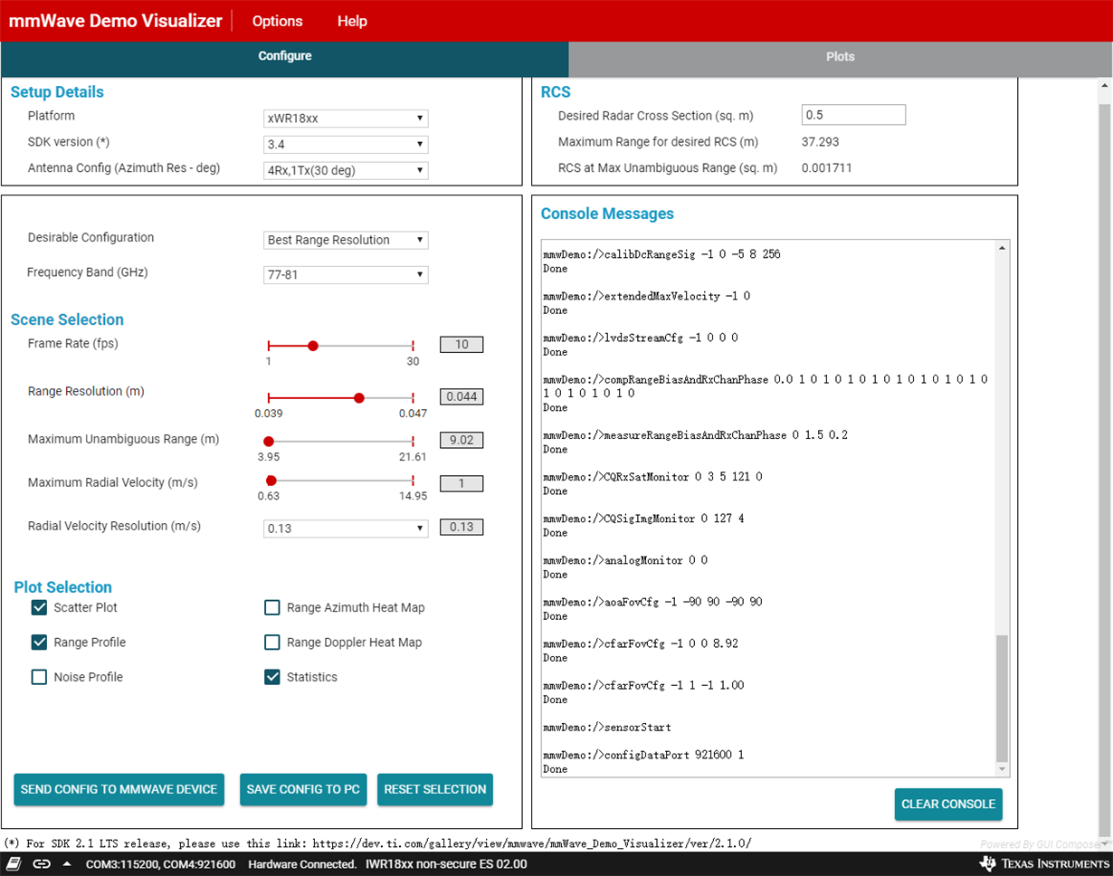
- testing via gui, Configuration is as follows:
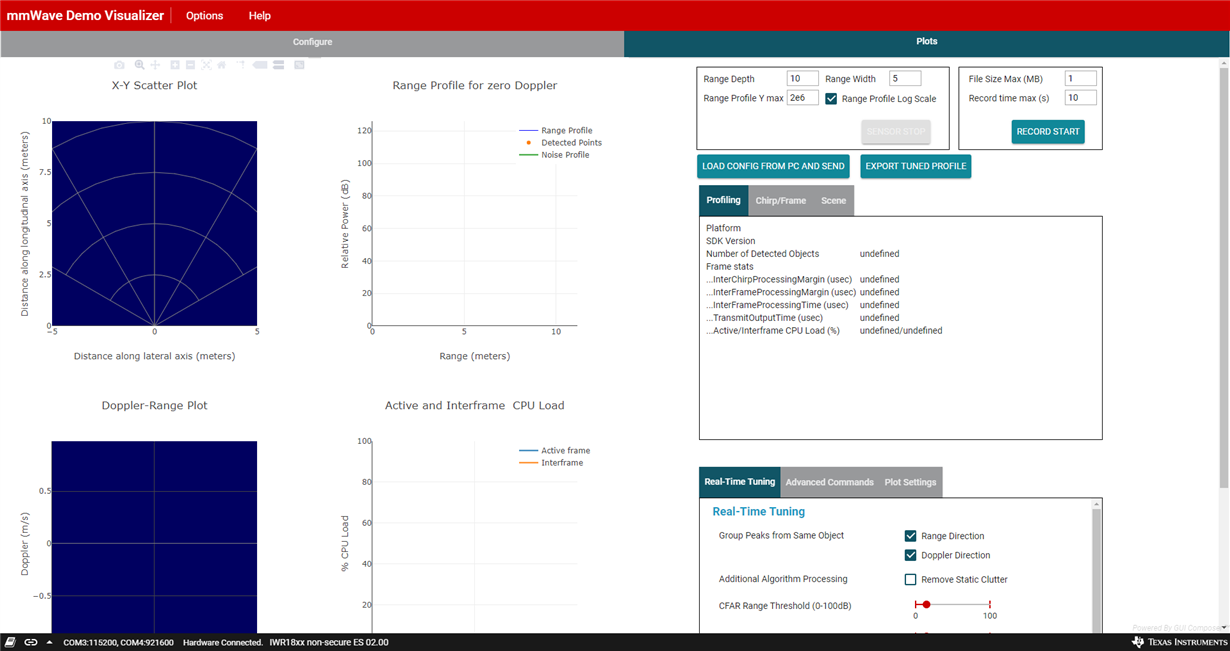
- then clik to the plot, we see no target graphic display. Can you tell me what the problem is ? thanks.


I think it is the error of CLI sent by the serial port, so I tried to debug the serial port.
the CLI config is,
% ***************************************************************
% Created for SDK ver:03.04
% Created using Visualizer ver:3.4.0.0
% Frequency:77
% Platform:xWR18xx
% Scene Classifier:best_range_res
% Azimuth Resolution(deg):30
% Range Resolution(m):0.044
% Maximum unambiguous Range(m):9.02
% Maximum Radial Velocity(m/s):1
% Radial velocity resolution(m/s):0.13
% Frame Duration(msec):100
% Range Detection Threshold (dB):15
% Doppler Detection Threshold (dB):15
% Range Peak Grouping:enabled
% Doppler Peak Grouping:enabled
% Static clutter removal:disabled
% Angle of Arrival FoV: Full FoV
% Range FoV: Full FoV
% Doppler FoV: Full FoV
% ***************************************************************
sensorStop
flushCfg
dfeDataOutputMode 1
channelCfg 15 1 0
adcCfg 2 1
adcbufCfg -1 0 1 1 1
profileCfg 0 77 916 7 57.14 0 0 70 1 256 5209 0 0 30
chirpCfg 0 0 0 0 0 0 0 1
chirpCfg 1 1 0 0 0 0 0 0
frameCfg 0 0 16 0 100 1 0
lowPower 0 0
guiMonitor -1 1 1 0 0 0 1
cfarCfg -1 0 2 8 4 3 0 15 1
cfarCfg -1 1 0 4 2 3 1 15 1
multiObjBeamForming -1 1 0.5
clutterRemoval -1 0
calibDcRangeSig -1 0 -5 8 256
extendedMaxVelocity -1 0
lvdsStreamCfg -1 0 0 0
compRangeBiasAndRxChanPhase 0.0 1 0 1 0 1 0 1 0 1 0 1 0 1 0 1 0 1 0 1 0 1 0 1 0
measureRangeBiasAndRxChanPhase 0 1.5 0.2
CQRxSatMonitor 0 3 5 121 0
CQSigImgMonitor 0 127 4
analogMonitor 0 0
aoaFovCfg -1 -90 90 -90 90
cfarFovCfg -1 0 0 8.92
cfarFovCfg -1 1 -1 1.00
sensorStart
and the iwr1843 download xwr18xx_ccsdebug.bin in advance, then enter Debug mode in CCS.

-
However, there are some errors when sending CLI instructions using a serial port:
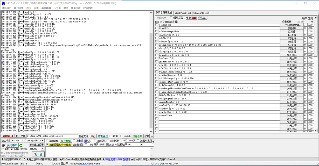
And no information is returned in the console window of the CCS debug environment.
Based on the above problems, I would like to ask for help. Thanks very much!

