This thread has been locked.

If you have a related question, please click the "Ask a related question" button in the top right corner. The newly created question will be automatically linked to this question.

CCS/TIDEP-01012: Hardware Design of Cascade Radar TIDEP-01012

Part Number: TIDEP-01012
Other Parts Discussed in Thread: MMWCAS-RF-EVM, MMWCAS-DSP-EVM, TDA2

Tool/software: Code Composer Studio

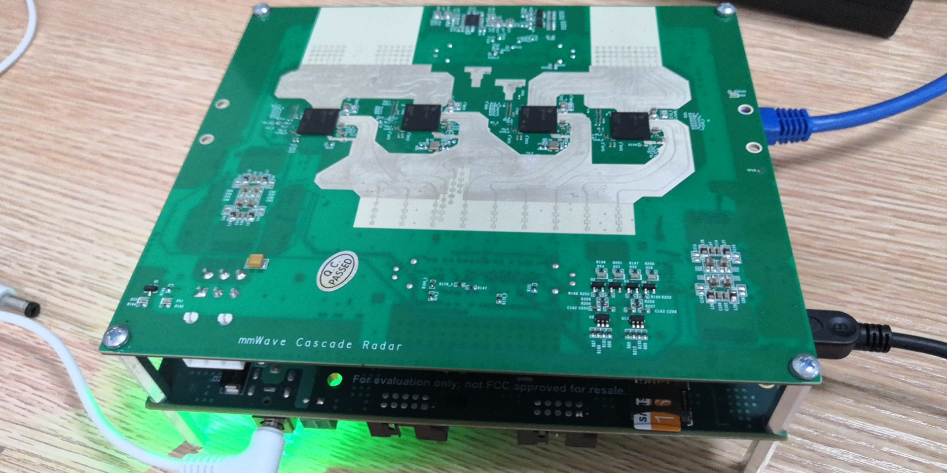
We designed and manufactured a cascade radar RF board according to the design scheme of TIDEP01012, but it is not powered after it is connected to the following signal processing evaluation module.

What should we do?

  • Hello,

    Can you please check if all the connections to the board are proper and the 12V power supply to the MMWAVCAS-DSP-EVM is also good.

    In addition to that, please ensure the Host board connection from the RF board to the DSP-EVM i.e TDA is not loose. The 5V power supply to the RF board comes from that only. 

    Let us know if the issue still persists.

    Regards,

    Ishita

  • Hello, Ishita

    We have checked that the Host board connection is not loose and the 12V power supply to the MMWAVCAS-DSP-EVM is also good.

    Are there any other steps to activate the the RF board?

  • Hello, 

    Do you have TI cascade RF board? If yes, can you please try connecting it to ensure the power supplies from the TDA through the host connectors is fine. This experiment could directly lead us to a conclusion if there's a problem with the RF board or the DSP EVM.

    Regards,

    Ishita

  • Hello, Ishita

    We have a cascade RF board, and have tested that  the power supplies from the TDA through the host connectors is fine.

    Is there any other problems?

    Thanks.

  • Hello,

    It seems there is something wrong with your custom board then. I'll transfer this thread to an expert.

    Regards,

    Ishita

  • Hello, Ishita

    Looking forward to your reply.

    Best regards.

  • Hi user6010015, 

    I would start with debugging the 5V to AWR LP87424P, power management IC (PMIC) regulators (reference designators U3 and U4). Those PMIC are setup in the MMWCAS-RF-EVM schematic to come out of reset and power sequence the AWR devices as soon as 5V is provided from the Host Interface connectors (J4 and J5), SYSTEM_5V0 power net. 

    From your photo, it does not appear that LED DS1 or DS3 are being enabled, even though the attached MMWCAS-DSP-EVM board is attached and powered on. This indicates to me that 5V (SYSTEM_5V0) is not being supplied from the J4 and J5 connectors for some reason.

    After good power is supplied to the AWR devices, you can move on to the other fundamental signals from the TDA2 host: reset, clocking and SOP select and the SPI connectivity. If all of that is good, the devices should boot and be mastered from the TDA2 host/mmWave Studio. 

    Please let me know what you find. 

    Thank you,

    -Randy

    Thank you,

    -Randy