This thread has been locked.

If you have a related question, please click the "Ask a related question" button in the top right corner. The newly created question will be automatically linked to this question.

IWR6843ISK-ODS: Reading recorded data from mmWave Demo Visualizer

Part Number: IWR6843ISK-ODS
Other Parts Discussed in Thread: IWR6843, AWR1642

Hello everyone,

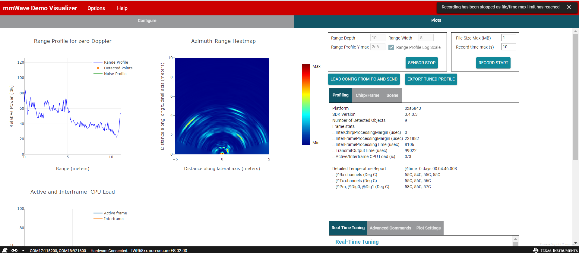
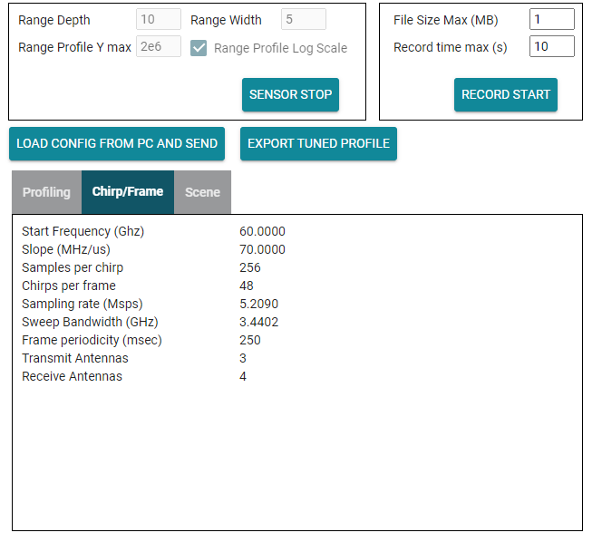
I am trying to read the .dat file recorded by the mmWave Demo Visualizer. I am starting from the "mmwave_read_complete.m" Matlab script just modifying the number of tx antenna tx_num to 3. The script does not work so I suppose it is not thought for the IWR6843ISK-ODS. Anyway, I am trying to make it working based on these instructions, C:/ti/mmwave_sdk_03_04_00_03/packages/ti/demo/xwr68xx/mmw/docs/doxygen/html/index.html – Section: Output information sent to host.

However, I have problems starting from the first lines. As an example, the first header information is the sdk version that in my case is “3.4.0.3” but the script shows: “7. .7.”

The script section for reading the header is:

function header=header_read(file)

version=fread(file,2,'uint16');

version=num2str(version);

version=[version(4) '.' version(3) '.' version(2) '.' version(1)];

total_package_length=fread(file,1,'uint');

platform=fread(file,1,'uint');

platform=dec2hex(platform);

frame_num=fread(file,1,'uint');

CPU_time=fread(file,1,'uint');

object_num=fread(file,1,'uint');

data_structure_num_in_package=fread(file,1,'uint');

subframe=fread(file,1,'uint'); % this part is different from the document


header={version;total_package_length;platform;frame_num;...

   CPU_time;object_num;data_structure_num_in_package};

Thanks in advance

  • Hi Emanuele

    Can you clarify which binaries you have flashed or software you are running on your IWR6843?

    Also can you specify from where you found this script?

    Regards,

    AG

  • Hi Akash and thank you for your answer. I found the script at the following link, but now I am not sure that is an official TI script. Anyway, I figured out that it is for TI AWR1642 and this is the reason why it needs some changes to be working for the IWR6843ISK-ODS

    https://github.com/lynnlilu/mmWave_reading

    This should be the path of the firmware in my computer:

    ti\mmwave_sdk_03_04_00_03\packages\ti\demo\xwr68xx\mmw\xwr68xx_mmw_demo.bin  xwr68xx_processed_stream_2020_07_23T16_08_12_245.dat

    The mmWave Demo Visualizer seems working properly with the board. I am also attaching the recorded file (10 seconds) and two screenshots of the Visualizer concerning configuration during the measurement.

    Best Regards,

    Emanuele

  • Former Member
    0 Former Member in reply to Emanuele Cardillo

    6153.understand_OOB_output.pdf

    Hello,

    the UART data format may have some variations between SDK versions. Here is a document explaiing the data format that correlates with SDK 3.4

    Amanda

  • Dear Amanda,
    thank you for your answer. Anyway, I modified the script according to the file but I noticed some problems. I properly read Frame Header, TLV Header and TLV Type Identifier. The data file that I attached in my previous message has the first type identifier equal to 2, i.e. the range profile. It has been properly read. The second type identifier is 4, i.e. the Azimuth Static Heatmap, but probably your file does not help. Indeed, it suggests to use a data length equal to (Range FFT size) x (Number of "azimuth" virtual antennas) x (4Bytes), that in my case is 256x12x4bytes=3072x4byte. A first inconsistency is that the length read from the TLV Header is 8192 (in byte)=2048x4bytes. By using 256x12x4bytes, the next type identifier becomes 524310 that actually is a wrong number. Concerning the Azimuth Static Heatmap the file says: “<rangeAzimuth(Elevation)HeatMap> is set to 1 AND demo is not for AOP or ODS which use AOA2D; occurs every frame” so I think there is another (different) file for my IWR6843ISK-ODS board.
    However, beyond this problem (maybe I am wrong, I do not know) I am observing that despite TI is a great and valuable company, the documents related to the different boards are too many and too fragmentary. I spent 10 days on this board without being able to simply read some measured files. I wonder why there is not an available script for directly reading the data recorded from the IWR6843ISK-ODS board.
    Best regards,
    Emanuele

  • Dear Amanda, 

    I have a new update/information. By searching within the available TI material, I found in the following link that a specific demo firmware exists for the IWR6843ISK-ODS, the xwr64xxODS_mmw_demo.bin.

    http://dev.ti.com/tirex/explore/node?node=AHUVfZLNUKWpA43MPJTM7Q__VLyFKFf__LATEST&r=VLyFKFf__3.6.2

    I would try to load this firmware for trying if something changes but I do not find it in the latest Industrial toolbox. Is it useful for my purpose?

    Best Regards

  • Former Member
    0 Former Member in reply to Emanuele Cardillo

    Hello,

    You should be using the ODS point cloud lab here: https://dev.ti.com/tirex/explore/node?node=AHUVfZLNUKWpA43MPJTM7Q__VLyFKFf__LATEST

    This is the ODS point cloud demo in the latest toolbox. 

    Amanda

  • Hello Amanda,

    thank you for your answer. I loaded the ODS point cloud demo and it works. The problem is the I need to record the range Azimuth Heath map that is not included by default.

    At the link you provided:

    https://dev.ti.com/tirex/explore/node?node=AHUVfZLNUKWpA43MPJTM7Q__VLyFKFf__LATEST

    you can read: "You can generate and save other configurations using the SAVE CONFIG TO PC button in the Visualizer but you will need to replace the compRangeBiasAndRxChanPhase command line in the saved config with the corresponding command provided in the config file included in this lab (profile_iwr6843_ods_3d.cfg). This is needed to adapt the saved configuration for the IWR6843ISK-ODS antenna pattern."

    Therefore, I selected range Azimuth Heath map, removing the flag in the other plot options and finally I replaced the compRangeBiasAndRxChanPhase command line with the original one but it does not work.

    Can you suggest the solution?
    Best Regards,

    Emanuele

  • Dear Amanda,

    finally, I got the Azimuth Heath map.

    I simply modified these two lines of the provided conf. file as follow:

    frameCfg 0 2 32 0 1000 1 0
    guiMonitor -1 0 0 0 1 1 0

    In frameCfg I modified the frame periodicity in ms to allow enough time for selected UART output to be shipped out. Although this should be a safe number, I would know what is the minimum allowed time when sending the Azimuth Heath map.

    In guiMonitor, the 5th bit should be the range Azimuth Heath map but I don't know why, I received the rangeDopplerHeatMap  instead. So I set both the 5th and 6th bits.

    I wrote this information for helping other engineers but if you can clarify my doubts, I think it can help.

    Emanuele

  • Former Member
    0 Former Member in reply to Emanuele Cardillo

    Emanuele,

    In the document I attached and if you refer to the SDK documentation for guiMonitorCfg you would see that for AOP/ODS antenna boards which use 2D AoA - the range-azimuth/elevation heatmap data is output when the 8th bit is set. The 5th bit gives you the range-doppler heatmap. This is assuming you are using the current SDK 3.4

    Amanda

  • Dear Amanda,

    I was speaking about the bits in the guiMonitor string. Anyway, thank you again for your answer.

    Emanuele