Part Number: IWR6843ISK-ODS
Other Parts Discussed in Thread: IWR6843AOP
Hello!
We have several questions concerning IWR6843ISK-ODS calibration.
1. It says on ti/demo/xwr68xx/mmw/docs/doxygen/html/index.html page that we must use profile_calibration.cfg from ti\demo\xwr68xx\mmw\profiles folder.
Is this profile and calibration results that we will get are universal? Is it right to apply calibration results (compRangeBiasAndRxChanPhase string) to any other profile config-file?
For example, in our own config-file we use all antennas and freqSlopeConst = 166, in profile_calibration.cfg freqSlopeConst = 156. To calibrarte our sensor to work with 166, do we have to change freqSlopeConst in profile_calibration.cfg from 156 to 166?
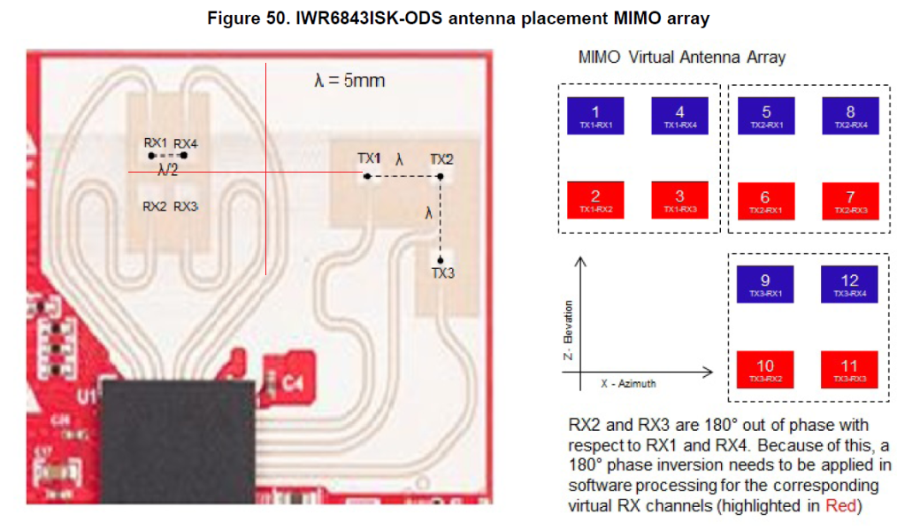
2. Which program should be loaded to IWR6843ISK-ODS during calibration? Do we have to use .xe674, .xer4f images from ti\demo\xwr68xx\mmw ? Or we can load our program? Is it matter that we use 2D Rx antenna pattern?
3. It says that we have to set a strong target at the distance of X meter at boresight. Were should we choose the center of our antenna system?
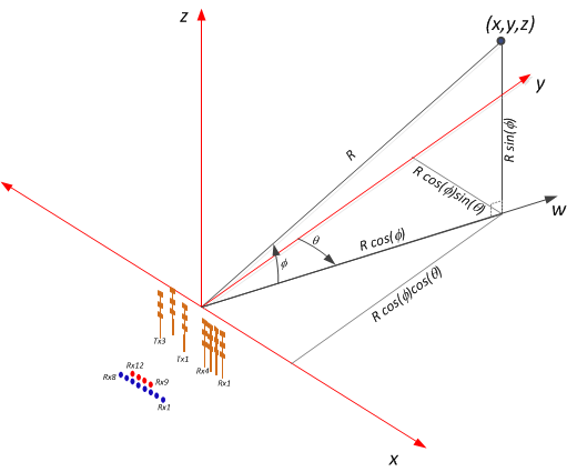
We have this antenna layout
Thank you for your reply.
__
Denis