Part Number: INA219
I have been trying out the INA219 and mostly, it has been working fine. I have come across an unexpected behaviour and I am am not able to work out what it is I have done (or not done) in my configuration. Basically, I am finding that when I apply a load above 1A i.e. 50% of the maximum, then the Base Voltage rises beyond what was expected.
Background
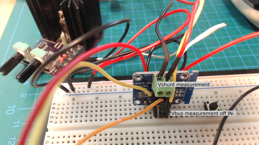
I am using the Adafruit INA219 breakout board. This is comes fitted with a 100 mΩ shunt resistor. I have a lab supply providing 7V to the INA219 IN+. The IN- is connected to a variable current sink. I have a 5V regulator supplying the control circuitry of the Current Sink. The AN219 is sourced by an ATTiny3217 Xplain Pro dev board 3.3V output. The connection is as per the diagram below. The reason for this odd configuration is that I wanted to see what would happen when the load voltage is greater than the rest of the system supply. Because if the issue I discovered, I have not pushed this any further just yet.

It might not be well depicted but the grounds are all connected. I have a Volt meter on the IN+ and IN- of the INA219 as well IN- to GND. I set the current sink to draw up to 1.5A in roughly 500mA steps - the single turn POT of the Current Sink does not allow for great accuracy in the steps. The current reading was taken from the Lab power supply. No Amp meter was connected at all anywhere.
Imax: 2A
V nominal: 7V
Rshunt: 0.1 Ω
Calibration: 0x1000
Configuration: 0x199F - BRNG 16V, /6, 12Bit, Shunt and Bus Continuous
Findings
What I found was that with this configuration, once the current sink was adjust to over 1A (on the Lab supply), then the Shunt voltage would be much higher that expected. The "current-measured" in the table below is, again, from the Lab power supply. "shunt-actual" is the result of the shunt register after applying the shunt LSB. "shunt-measured" is the reading from the Volt meter applied to IN+ and IN-.

Question
Based on the information given, I would like to understand if this is correct behaviour?
What I am thinking is that there is something not correct with the shunt resistor. I have been over the data-sheet and the shunt resistor training videos and notes but I can not see what could be wrong here.
In this case for a 7V supply with a maximum 2A, why can't this 0.1 mΩ still provide a correct result when after 50% of maximum load is reached?
Any ideas and contributions would be appreciated.
Steve.