This thread has been locked.

If you have a related question, please click the "Ask a related question" button in the top right corner. The newly created question will be automatically linked to this question.

LMP91200: Have problem with LMP91200

Part Number: LMP91200

Hi everyone.

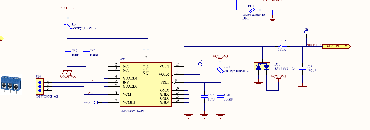
I had designed schematic using LMP91200 to communicate with PH sensor.

try to change PH value but ADC value i read not change.

i have probe at the pin INP of PH sensor, when i don't plug in PH sensor it is 1.6V and Vout is same Vin, i can't understand why it is 1.6V when i don't plugin PH sensor.

when i plugin Vin PH is 1.73, and Vout is 1.73?

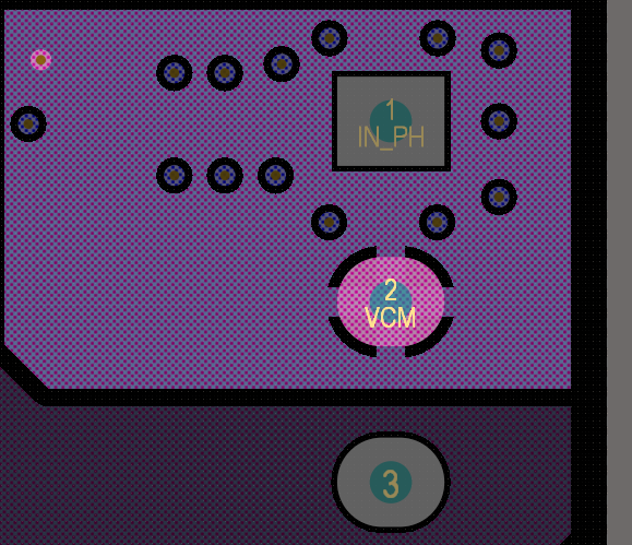
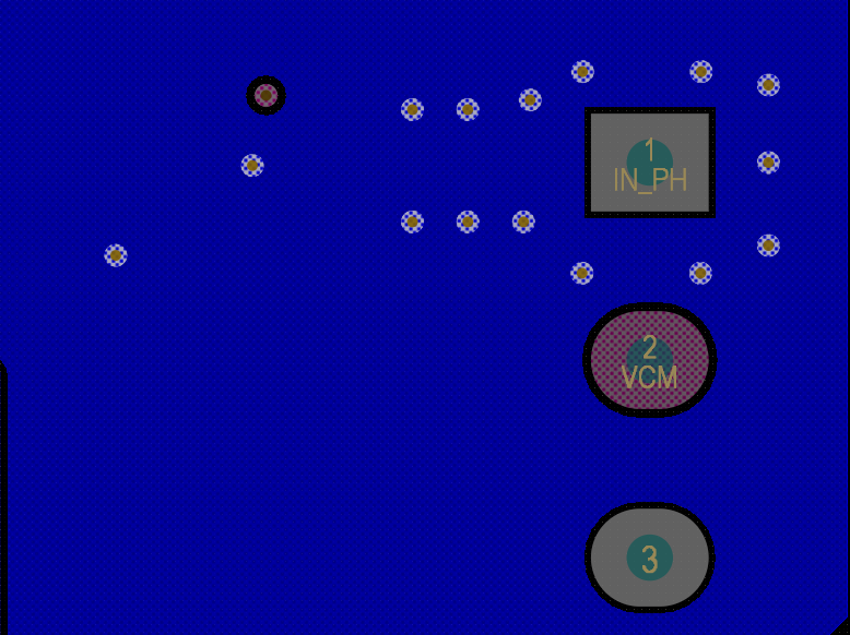
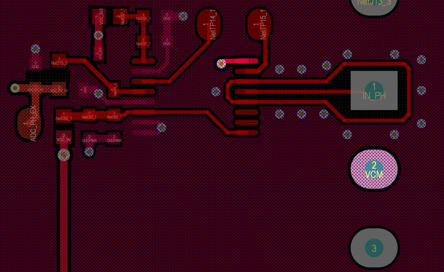
Schematic and layout as bellow.

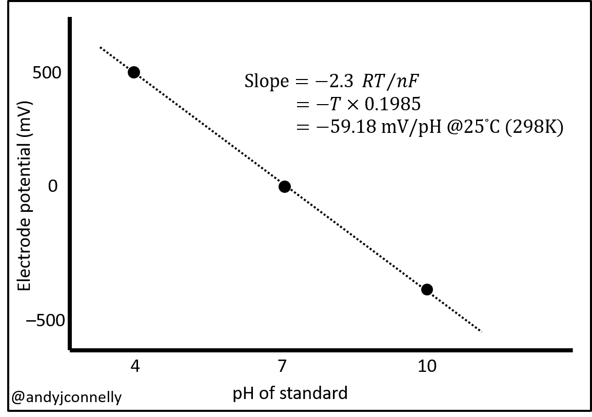
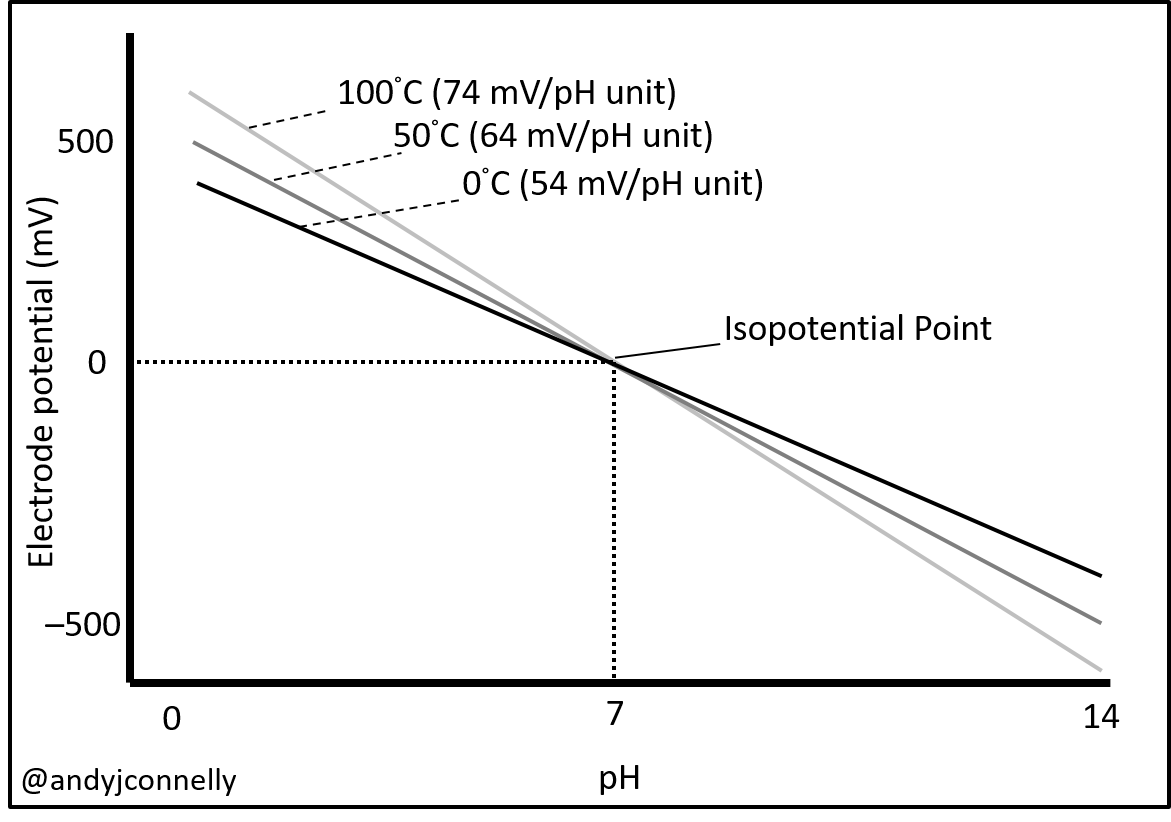
how i can calculate and measure PH value?

but it not successful.     

  • Dear Hoang - 

    Thanks for posting!

    I would remove/DNI the BAV199 part from your schematic. Also, what is the number of your sensor? - might want to put that on your drawing, next to the connector - that you should consider changing to use triax cable. 

    Also, perhaps consider connecting the VOCM output to another ADC channel and characterize, or adjust/remove the R47 and C54 as required by your MCU ADC. 

  • Hi Josh.

    Thanks for your respond.

    i have removed some component as you suggest, but this issue still happen.

    I only using 1 PH sensor : 

    I have changed to use triax cable, but it not solve.

    I have test my PH sensor with other device (PH kit of DFrobot) it is ok, that means Signal R57 to MCU is ok and PH sensor is OK

    What should i do in the next step?

    How can i calibrate PH and calculate PH value?

    Thanks and best Regards.

  • Hoang - 

    Perhaps i see it now - shouldn't your guard and VCM traces be at same potential - looks like you may have not connected them  - see the LMP91200 EVM schematic here to refer to. https://www.ti.com/lit/ml/snau122a/snau122a.pdf (page 6)

    then also make sure you have checked out this from the probe vendor, too - in case you modified the cable - as from them it should have SMA connector with an SMA to BNC adapter. https://www.atlas-scientific.com/files/pH_probe.pdf 

  • Hi Josh.

    Thanks for your respond.

    i'm not understand about "shouldn't your guard and VCM traces be at same potential - looks like you may have not connected them", because i have traced VCM and Guard in difference layer, can you explain more a bout it?

    In my case, i'm not modified cable, i only change BNC adapter to SMA.

    Really, i try to understand how to get correctly PH value, but i don't know about how to calculate it,

    in my schematic i used VDD=5VDC, Vref =3V3DC

    i saw that on the datasheet LM91200  have a formula : 

    E = Eo + (2.3 RT/nF) log aH+

    where:

    • E is the measured potential from the sensing electrode -> ADC value i will read directly form LM91200-> that right?

    • Eo is related to the potential of the reference electrode -> It is Vref (3.3V)-? that right?

    • (2.3 RT/nF) is the Nernst factor,

    • log aH+ is the pH, (aH+ = activity of Hydrogen ions). -> That means log aH+ is the pH value (0-14) i need to find?

    Beside that i saw: The output of a pH electrode ranges from 415 mV to −415 mV as the pH changes from 0 to 14 at 25°C, that means every PH probe have same this spec?

    Thanks And Best Regards.

  • Hoang - 

    Sorry, you are correct, the Active Guard pins should be at same potential as the INP pin. Please see section 10.1 in the LMP91200 datasheet (page 17) for the complete explanation. 

    And if you have a look at pages 6 and 7 here, you can see how our EVM is laid out and copy that. https://www.ti.com/lit/ml/snau122a/snau122a.pdf

    Regarding the formula - yes, logaH+ is what you are solving for. if you look on page 7 of the probe that you are using datasheet https://www.atlas-scientific.com/files/pH_probe.pdf, they simplify the formula for you, if that is helpful. 

    On our EVM, we used 3.3 for VDD and 2.5V regulator for VREF and in the datasheet, all the data presented there was with VDD and VREF @ 3.3VDC and the output is VOUT, as compared to VOCM. 

    @ 25C, your slope should theoretically look like this: 

    and over temp, it will theoretically look like this

  • Hi Josh.

    thanks you so much for your explain.

    -i saw that un the datasheet: we have a formula:

    E=Eo + (2.3RT/nF)log aH+.

    but in your replay, i saw slope = -2.3RT/nF and -59.18mV at 25oC, but follow the datasheet i saw it is 59.16 at 25oC. Do you have any misconception in this point.

    - can you explain more detail about paraneter in the formula? as i know:

        E = value from pin VOUT of LM91200 that is right?

        Eo is reference electrode voltage. i don't understand this parameter, how can i calculate this parameter or where i can get it?.

    - finally do we have any difference between use Vref =2.5V and Vref=3.5V

    it is good if you can share with me your example about calculate pH value reality feild using LM91200.

    Thanks and Best Regards.

  • Hoang,

    E is your measured value

    Eo is the zero that you set based on the reference. (if the reference is 3.2V then the zero is 1.6V)

    The Nernst factor is a slope defined as 2.3 RT/nF. if you use a negative slope you will get a -59.18mV at 25oC if you define the slope as a positive then you will get a 59.18mV at 25oC. The ratio of the slope does not change. it's still 59.18mV at 25C.

    it doesn't mater what you set the reference to.This value will matter if you have a 2.048V VREF on your ADC, then you may want to adjust the VREF of the LMP91200 to keep the zero or negative reference in the middle of your ADC VREF to get a wider and balanced output zero.

    E = Eo + (2.3 RT/nF)log aH+

    where

    • E is the measured potential from the sensing electrode,

    • Eo is related to the potential of the reference electrode

    ,• (2.3 RT/nF)is the Nernst factor,

    • log aH+ is the pH, (aH+= activity of Hydrogenions)

    Because you are not using a differential ADC, you will have to calculate the measured value by subtracting the zero to get a real measurement.

  • Hi .

    Thanks for your respond.

    Because i'm using STM32 to read ADC from LMP91200, VREF STM32 i set 3.3V, it is same VREF LMP91200, ADC resolution i used 12 bit =4096.

    I have tested again om my PCB (Schematic i have posted last time), 

    i'm using formula as bellow:

    volt = (value)*3.3/4096;
    pHvalue = ((volt - 1.65)*1000)/59.18;

    + Value = VOUT (Pin VOUt of LMP91200)

    + 1,65 is Eo, because VREF = 3.3V

    + 59.18 is  Nernst factor at 25oC

    But pH value i readed is 4 although i used pH liquid is 7 to test.

    I'm don't know where is my mistake in this formula?

    If i connected pin VCOM of LMP91200 to pin ADC of MCU then Eo = VCOM? and that can reduce more noise ?

    (2.3 RT/nF)is the Nernst factor, can you explain to me more detail about "n" in this factor, i saw that n=1 at temperature = 25oC, but if temperature # 25oC how can i find "n"?

    Thanks and Best Regards.

  • Hoang,

      Yes, your formula is wrong.

    E = Eo + ((2.3 RT/nF) * log aH+)      [solve to get the voltage from a ph]

    ph = 10^((E-Eo) / 2.3 RT/nF)      example:    ph = 10^((1.700-1.650) / 0.05918)    [solve to get the ph from the voltage]

    This should help

  • Hi .

    Thanks for your advice.

    I have used your formula: ph = 10^((1.700-1.650) / 0.05918):

    In my PCB, when i test with pH=7, i measured VOUT=1.8V that meanz pH value i readed about >200.

    i have checked again but these value not change VOCM =1.65V and VOUT =1.8V.

    Can you tell me: Where is my wrong in my schematic or PCB layout?

    Thanks and best regards

  • Hoang,

      I am running the numbers. I should have an answer soon.

  • Hoang,

      I would like for you to remove D15 diodes and remeasure the VOUT with a ph7 standard.

    The ph probe is designed to deliver 0mV at ph7. reference to the set zero. That means that you should have 3.3V REF = 1.65V zero = 1.65V ph7.

    The formula I gave you previous was the invert of the E formula. That formula will not provide you with the ph level. I have calculated the correct method to get the ph and added the temperature correction. However this formula doesn't work  with your ph VOUT of 1.8V, unless an offset error is added to the formula. This may very well be correct for calibration. I will continue to verify the formula if you can please provide the measured ph7 voltage with the diodes removed.

  • Hi. 

    Thanks for your help.

    I have removed D15 and tested again with with a ph7 standard.

    I have measured VOUT = 2V and VOCM  =1.657V, temperature in my area = 28oC.

    PH sensor i used for test: 

    This Sensor or my PCB is ok, because i have test with an other PH module : 

    Thanks and best regards.

  • Hi. 

    Until now. i'm not solve my problem.

    can you give me more advise to struggle with them?

    Thanks and best regards

  • Hoang,

      I have been working on this.

    Try this:

    Calculate the Neenst Factor to get temperature correction

    2.303 RT/nF 0.05917001 slope Nernst factor temperature corrected

    Constant
    R 8.314462618 J/mol K R = gas constant, 8.314 J/mol °K
    K 298.15 °K T = temperature, in °K (T°C + 273.15)
    n 1 n = Stoichiometry number of electrons in the reaction
    F 96485.33212 C/mol F = Faraday constant, 96,485 C/mol

    Then calculate the ph:

    ph = ((E-Eo) + Er) / (2.303 RT/nF) + 7 solve to the ph from the measured voltage
    E = measured voltage
    V7 = Voltage at ph 7 standard
    Nerst Factor = slope
    7 = Reference ph

    The method is based on Ph7 is = 0mV Then using the Nernst factor to calculate the ph value from 0mV.

    Let me know how this works for you.

  • Hi. 

    Thanks for your help.

    As your formula:

    pH = (((2 - 1.65) + Er)/0.05917) + 7.

    2 =  measured voltage at VOUT pin

    1.65 = measured voltage at VOCM  pin

    0.05917 = Nernst factor temperature corrected at 27oC

    7 = Reference ph.

    so What is Er in that formula?

    Thanks and best regards.

  • Hoang,

      My apologies, Er it the Error. If you measure VOUT at ph7 then subtract Eo, then you have an error correction. Remember ph7 should be 0mV, so if the measured voltage is 1.8V at ph7, and the zero is 1.65V, then you have an error of 150mV. This is your Er (error). It will allow you to zero ph7 by removing the error.

  • Hi. 

    Thanks for your help.

    I seem face with other problem, because when i calibrate with pH = 7 as you formula, after that i  have changed pH = 4, but measured voltage in VOUT pin have been not change. that mean VOUT always  = 1.8V although i changed pH =7 or pH =4.

    Do you think my schematic or PCB have problem?

    Thanks and best regards.

  • Hoang,

      I have looked over your schematic and layout. I don't see anything wrong.

    Check your board for cleanliness, make sure there is no flux residue on the board. These probes operate in the uA range and any contaminates will cause problems. Make sure after cleaning that you bake the boards to drive out moisture. even condensation will effect the probe.

    Also can you try another probe in case this one has a problem?

  • Hi .

    Thanks you for your support during i'm facing with my problem.

    I'm will make new PCB and replace connector with BNC and test again.

    If i have same problem, i will come back

    Thanks and best regards.