This thread has been locked.

If you have a related question, please click the "Ask a related question" button in the top right corner. The newly created question will be automatically linked to this question.

IWR6843: Data extraction from binary data

Part Number: IWR6843

Hi Team,

Thank you for your support.

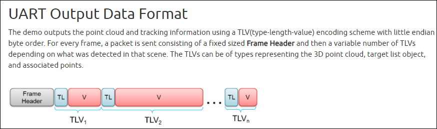
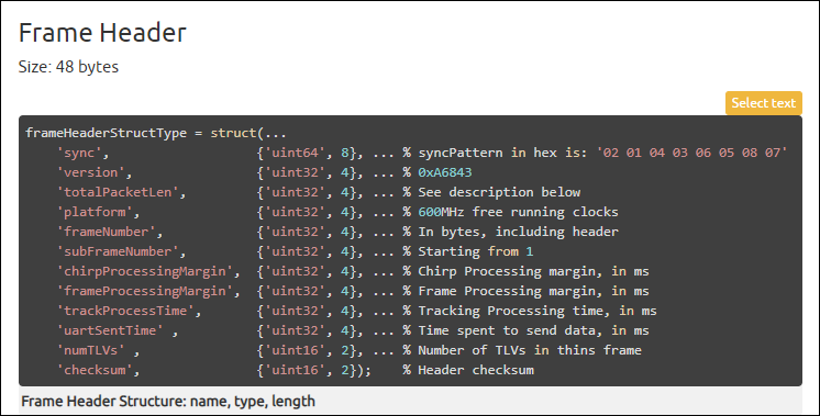
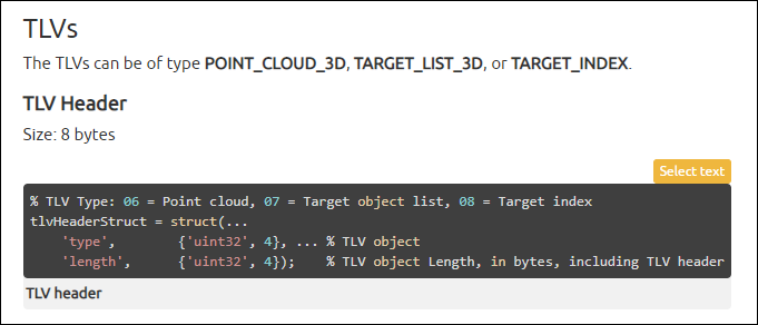
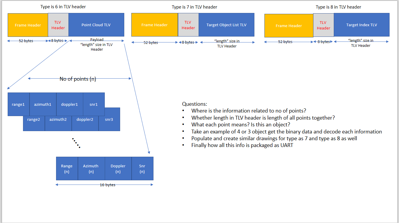
I have binary data, which is available in people count document. i want to identify the data from that binary frame. here i am attaching data format screenshot. i want to know, how the data is captured. for example here we took people count scenario. how people is counting using mmwave sensor and TLV's is formed. in the screenshot the data is repeated it means number of objects. what is the mean of point_cloud, target_objects and target_index. i am attaching one more screenshot that is my assumption, is this right way to represent. Please do the needful.

Regards,

Srikanth

  • Hello,

    Wonder if you have already looked at this guide that calls out the details of TLV size

    Data Formats

    You may have to reverse compute the count based on tlv size.

    If you look at the algorithm details it would show that:

    Point cloud :  input to the tracker.

    Target list : Out put of tracker.

    Another way to look at how data is parsed is to see the  python gui code which may provide insights to this.

    Thank you,

    Vaibhav

  • Thanks for your update.

    I couldn't find how the data is coming from the sensor and how the number of detected objects is converted to that GUI to see the data. my point here is before we see the data into GUI, I want to understand how data is looking like. once I did it this step, I can do any project with my custom board. See the above screenshot, every detected object, how data format looking like. every time frame header is repeated or TLV's are repeated. As per my understanding, every detected object frame hearer and TLV's are repeated and where is the number of points in the point cloud. how can I identify in binary data format? Please do the needful.

    Regards,

    Srikanth

  • Hi Srikanth,

    You have not indicated which particular people counting demo you are looking at. But each demo has clear description of the output stream including the message header and description of the individual TLVs, with the actual data structures as shown below. These definitions and the parsing code implented in the python GUI should be a complete reference on how to interpret the output stream.

    and so on... 

    Regards

    -Nitin

  • Thank you.

    but this data is send through UART communication right. i found 3 UART communication in uart_xwr68xx.c file. which UART is used finally for sending data on SMT connector. UART 1 and 3 used for SUBSYS_MSS. UART 2 for SUBSYS_DSS. i have checked respective codes, but i didn't find. please do the needful.

    Regards,

    Srikanth

  • Srikanth,

    There are two UARTs on the MSS side as used in the source code shown below (mss_main.c). The control UART which is used to send the configuration commands to the sensor and the Data UART (i.e. the logging UART) which is used to send the data out from the sensor. The DSS UART is not connected on the TI EVM and nor is it used in any demos. All data is sent out from the MSS logging UART. 

        /*****************************************************************************
         * Open the mmWave SDK components:
         *****************************************************************************/
        /* Setup the default UART Parameters */
        UART_Params_init(&uartParams);
        uartParams.clockFrequency = gMmwMssMCB.cfg.platformCfg.sysClockFrequency;
        uartParams.baudRate       = gMmwMssMCB.cfg.platformCfg.commandBaudRate;
        uartParams.isPinMuxDone   = 1;
    
        /* Open the UART Instance */
        gMmwMssMCB.commandUartHandle = UART_open(0, &uartParams);
        if (gMmwMssMCB.commandUartHandle == NULL)
        {
            Pcount3DDemo_debugAssert (0);
            return;
        }
    
        /* Setup the default UART Parameters */
        UART_Params_init(&uartParams);
        uartParams.writeDataMode = UART_DATA_BINARY;
        uartParams.readDataMode = UART_DATA_BINARY;
        uartParams.clockFrequency = gMmwMssMCB.cfg.platformCfg.sysClockFrequency;
        uartParams.baudRate       = gMmwMssMCB.cfg.platformCfg.loggingBaudRate;
        uartParams.isPinMuxDone   = 1U;
    
        uartParams.dmaHandle      = dmaHandle;
        uartParams.txDMAChannel   = UART_DMA_TX_CHANNEL;  
        uartParams.rxDMAChannel   = UART_DMA_RX_CHANNEL;  
    
        /* Open the Logging UART Instance: */
        gMmwMssMCB.loggingUartHandle = UART_open(1, &uartParams);
        if (gMmwMssMCB.loggingUartHandle == NULL)
        {
            System_printf("Error: Unable to open the Logging UART Instance\n");
            Pcount3DDemo_debugAssert (0);
            return;
        }

    Please go through the visualizer code to understand the parsing as indicated below and let us know if you have any specific questions.

    -Nitin

  • Thanks for your update.

    Regards,

    Srikanth