This thread has been locked.

If you have a related question, please click the "Ask a related question" button in the top right corner. The newly created question will be automatically linked to this question.

TMCS1101: AC Power Measurement

Part Number: TMCS1101
Other Parts Discussed in Thread: MSP430I2021, EVM430-I2040S, TMCS1100

Dear *,

i want to measure AC power ( AC voltage x AC current ) ( digital sampling) for non linear loads ( current is non sinusoidal).

AC voltage 230V 50Hz MAX ±16A

1) which part from the Device Comparison Table TMCS1101 is best to use for ±16A max?

2) what is the smallest current that i can detect and measure? and what is the current step if 5V supply is used?

3) can we also use 3.3V supply with TMCS1101?

4)  what is the sensing delay of the TMCS1101? ( i want to sample voltage and current in the same time to get accurate AC power in time)

4a) if i have resistor divider to measure AC voltage connected to ADC of MSP430 -> for voltage sense there is no delay is that correct?

4b) and for AC current i have TMCS1101 , the output is connected to ADC of MSP430 -> here the TMSC1101 cases a delay is that correct?

Is it possible then to synchronize the AC voltage and AC current measurement, so that we get the AC voltage sample and AC current sample in the same time?

5) do i need zero cross detect of AC voltage  to synchronize the two ADC ?

Best Regards.

  • Hello ZeroD,

    Thanks for considering to use Texas Instruments.

    1)  I think your best option comes from whichever device utilizes the most linear range. For ±16A, devices A3B and A4B are eliminated as those will rail out before your max load is reached. This leaves A2 as the gain variant with the highest usable resolution for your measurement.

    2) If you do not calibrate for output offset voltage, you should plan to sense currents higher than (10 x output offset voltage error)/gain. For A2B that would be (10 x 1mV)/(100mV/A) =100mA


    3) According to the recommended operating conditions table, 3V is the minimum supply that can be used. Therefore you should be able to use a 3.3V supply.


    4) The TMCS1101 has a sampling integrator that updates the output every 4us.

    4a) Can you provide a diagram of how you are wiring the divider to the ADC? Without seeing your schematic, I would expect there to be no delay from a divider so long as you didn’t have a big capacitor connected to it.

    4b) For a 50Hz signal, you shouldn’t see a delay.

    5) The ability to synchronize measurements depends on your microcontroller. I would recommend you posting another question to the forum with the microcontroller you intend to use. That way it will be directed specifically to the team that supports them.

  • Hi Patrick,

    thank you for the feedback

    4)a) i was referring to connection as in TIDU454A page 5 Figure 3

    4b) how do you meant there will be no delay ?, but the current is from non linear loads, and has harmonics , what about those, to what harmonic there will be no delay?

    I want to change from Rshutn to hall sensor or CT to reduce the power losses on rshunt, and also then  there is the benefit of isolation. 

    4c) Also i fond for CT that it has digital phase shift (SLAA122), does the TMCS1101 also have digital phase shift ?

    4d) if i use CT or hall sensor for current sens and have isolation , what is the best way to isolate voltage sensing without to introduce delay or phase shift ?

    Isolation amplifier will probably introduce delay? I don't know a bout the isolation transformer will it also introduce delay like the CT?

    5) I will use MSP430 for metering like MSP430I2021

    Best Regards.

  • Hello ZeroD,

    Thank you for providing that additional information.  I need to investigate a little further before I can properly address some of your questions, I also may need to pull in a representative from the microcontroller product line to better address questions involving the MSP430I2021.

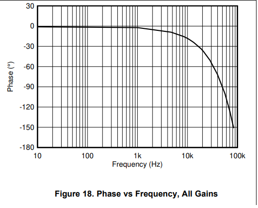
    Aside from the 4us integrator delay, there is phase delay which is as in the graph shown below.

  • Hello ZeroD,


    4a) There is conversion time delay. I need to check with the microcontrollers representative to determine if there is any phase delay.

    4b, 4c) Initially I was only considering your fundamental harmonic. For higher frequency harmonics I think the phase plot I shared above should help determine what kind of phase delay you can expect.

    Im not an expert with CT and the author of that application report does not appear to be with TI anymore. However, from my understanding of the article, the proposed technique with an FIR filter introduces a digital delay for the purpose of compensation and calibration of the phase shift introduced by the transformer.

    4d) As for the best method, I cannot say. If you use a current transformer, from what I have read your secondary load has a significant impact on the phase shift through the transformer. Lower resistance on the secondary is better. As for our Hall device, operating at least at frequency 1/10 below our bandwidth is advised.

    5) The zero crossing in the TIDU454A is for determining whether to use a DC or AC measurement routine.

    As to your previous question about getting AC voltage samples and AC current samples at the same time, according to the MSP430i2xx Family User's Guide the all of the ADCs work simultaneously so you should be able measure both current and voltage at the same time with the technique outlined in TIDU454A.

  • Hello,

    For the EVM430-i2040S, the voltage divider (voltage sensor) and shunt (current sensor) do not introduce a phase shift ideally. However, the passives (e.g. anti-aliasing filters) will most likely. The SD24 ADC in MSP430i2021 features preload which can delay one ADC channel with respect to the other to effectively zero out this phase shift. Preload is fractional delay and if not enough, whole sample delays must be implemented in software.

    If you want to use a CT, yes they may also introduce some phase shift that gets added or subtracted to the passives' phase shift. I wouldn't worry about this phase shift since it's removed by adjusting the preload and/or whole sample delays to align the voltage and current samples. All this is done automatically using our Energy Measurement Design Center GUI and software library.

    Regards,

    James

  • Hi James,

    thank you for the replay.

    I was thinking to use voltage transformer before voltage divider for voltage, and hall sensor instead of shunt for current, to get the isolation.

    1)

    Reading your replay above the voltage transformer and hall sensor will also introduce phase delay is that correct? To confirm, this can be handled in software with Preload or sample delay in software?

    2)

    My second question is if i use voltage transformer or current transformer or hall sensor instead of voltage divider and current shunt , will the bandwidth of the isolation devices impact on current harmonics because of nonlinear loads, and how? Also to confirm the anti aliasing has a bandwidth that will limit to sample current harmonics? What is the proper way to design the antialiasing filter?

    3) 

    So in order to get the highest bandwidth the best solution is voltage divider and current shut? But the this is not isolated approach and if the device is in plastic housing with double isolation do we need to do isolation of measurement of voltage and current? I'm asking this because in TIDU454A for single phase AC monito you also didn't propose isolated way for measuring voltage and current.

    4) one question regarding TIDU454A, what is the sample trigger for ADCs on page 3 figure 1 ? IS it the Vac voltage zero crossing ?

    Best Regards.

  • Hello ZeroD,

    1) Both the transformer and hall sensor will introduce some phase delay. For the TMCS1101, according to the data used to generate the curve above, the phase will rapidly increase for any signal content above 1khz.  As for the transformer, the manufacturer for that transformer may be best able to give you an idea of what to expect and how to minimize it.  Based upon the phase delay you either calculate or determine experimentally, you can use the preload delay or a combination of the preload delay and sample delays.

    2)The bandwidth of the devices will attenuate the higher harmonics.  I will let James comment how best to address antialiasing with the microcontroller.

    3)If you are wanting to capture all the frequency content well above 50Hz, we have several current shunt monitors with higher bandwidth than that of the TMCS1100 or even isolated amplifiers.

    4) Perhaps James may say otherwise, but I think the sample trigger is initiated by a software routine and executed when the instruction directing the ADC to start sampling passes through the processing pipeline.  After the sample trigger and several subsequent samples, the number of zero crossings are assessed for determining if an AC or DC signal is getting sampled.

  • Hello,

    I'm going to address your first question before we move on to the others. Discussing four topics in parallel may be more efficient but I don't think it's adding enough clarity here. Technically, each of these questions should be a unique thread. Please keep that in mind moving forward.

    ZeroD said:
    I was thinking to use voltage transformer before voltage divider for voltage, and hall sensor instead of shunt for current, to get the isolation.

    I don't have much experience with hall effect sensors, but this sounds reasonable. However, this approach is probably more expensive overall than just using a voltage divider to measure voltage and a shunt to measure current. Keep in mind that you can add isolation on the front end (e.g. sensors) or the back end (e.g. communication). Why don't you just isolate the communication like what's done on the EVM430-i2040S?

    Please confirm that this makes sense before we continue with the next question.

    Regards,

    James

  • Hi James,

    First i wanted to isolate the front end because of safety, but then i saw that it has some drawbacks:

    FrontEnd pros: isolation at AC-Mains, Reduced dissipation for current measurement if replacing Rshunt with hall sensor.

    FrontEnd cons: all the isolation components introduce delay and have limited bandwidth, it will increase the price, question if it is good-enough for measurement of current of the non-linear loads, also need to isolate the AC/DC power supply used by the MCU that is doing measurements.

    But then my device will be in plastic box and will have only Wifi communication to outside world. I'm not yet shore what are the regulation for those device but i think i don't need to isolate nor the measurement nor the communication, what do you think?

    To confirm your statement we can continue so that we don't isolate the front-end because i think this approach is better for non-linear loads in terms of accuracy and capturing as much harmonics as possible.

    The voltage divider and shunt will introduce smallest delay and will have highest bandwidth is that correct?

    The main idea of the device is to accurately as possible measure AC power  ( active, reactive, power factor ...) of non-linear loads and send it over Wifi.

    (from 100mA or lower up to 16A -> i'm not shore what range can be achieved with Rshunt and MSP430?)

    Best Regards,

    D.

  • Hello,

    ZeroD said:
    But then my device will be in plastic box and will have only Wifi communication to outside world.

    I don't think you need isolation, but if you want to provide isolation between the metering portion and the Wi-Fi module, then you could simply isolate the communication between the two devices (e.g. opto-isolators).

    ZeroD said:
    The voltage divider and shunt will introduce smallest delay and will have highest bandwidth is that correct?

    This configuration is adequate for most customers that I've supported.

    ZeroD said:
    (from 100mA or lower up to 16A -> i'm not shore what range can be achieved with Rshunt and MSP430?)

    Our devices can achieve a 2000:1 dynamic range (and higher if two channels are used). This means they can measure a range from 100 mA to 200 A. The EVM430-i2040S uses a 0.5 mOhm shunt which supports up to 15 A. I would recommend getting started with that and adjusting it later depending on your specific requirements. For shunts, you want to pick the resistance based on the maximum current and the maximum ADC input voltage. Obviously, a higher resistance will consume more power but will output a higher voltage. It's a balance.

    Regards,

    James