This thread has been locked.

If you have a related question, please click the "Ask a related question" button in the top right corner. The newly created question will be automatically linked to this question.

IWR6843: PLL not lock when power up

Part Number: IWR6843

Hi expert,

Customer made their own board followed our 6843ISK-ODS design. The power supply is 87702+5301. But sometimes 6843 could not power up correctly after power reset.

They measured 1.0V, 1.2V, 1.8V and 3.3V to 6843 when power up but didn't find problem. SOP is  also set to 101 (3.3V) correctly.

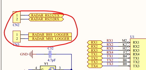
They could not get correct clock input from crystal, WARMRST is pull down for only 1~2us (not ~8us in crystal mode) and there is no output on 1V4_APLL. 

I asked them to change external clock source and it still failed.

The PLL or oscillator may not be driven correctly inside 6843 but i checked their schematics and no problem was found.

Could you please give some suggestion to debug the board? 

Thank you.

Regards,

Allen

  • Hello Allen,

        We need bit more information to understand the problem...  What application is being run? Which version of silicon being used? Which SDK framework is being used?  Is this problem is occasional or always seen? 

    What is the difference between TI EVM and custom hardware? 

    What is the status of NERROROUT, Is it high or low? If it's low then there seem to be hardware fault that need to be looked at. 

    Please refer below xWR6x43 Checklist for Schematic Review, Layout Review, Bringup/Wakeup and go to "HW bringup guidlines" section and review if there is any discrepancy.

    https://www.ti.com/lit/zip/swrr161 

    Thanks and regards,

    CHETHAN KUMAR Y.B.

  • Hi Chethan,

    It's in boot stage, no s/w image in flash. Silicon version is IWR6843 2.0 production. After nreset is pulled down and up, they don't see the crystal generates clock on CLKP and CLKM.

    It almost failed all the time. We can see the NERROUT is low and compared the schematics and checklist but did not find issues right now. I will ask customer if they already complete HW bring up check.

    Regards,

    Allen

  • Hi Chethan,

    Customer followed HW bring up guideline tests in the check list and they found the tests before T3-8 are pass while T3-8 failed. After nreset is pull down and up, no clock on crystal when SOP is set to 101. WARM_RESET output is down for 1-2ms. The voltage on 1P4V_APLL is 50~60mv and VOUT_PA is 1.0v. Most of times NERROUT is 1.

    I think the CLK or PLL module in 6843 does not start correctly when power reset. But i don't know the root cause because i can't find any issue on the schematics. I doubt if this is caused by PCB manufacture or BGA soldering. 

    Attached please find customer's schematics and kindly give me your advice about the h/w design. 

    Thank you.

    6648.sch.pdf

    Regards,

    Allen

  • Allen,

         I see one big issue is that, VBGAP capacitor has 47uF capacitor, it needs to be 47nF.

    This would cause delay in the Bandgap power up and subsequently all the stages of Analog/RF system power up gets delayed. Boot system checks during the power up if these values are not settled to the expected state, then device may not power up correctly.  

    Other minor observations are: Load switch resistor by default need to be opened. 

    Cautionary note: Below RS232 and logger pins are connected to external I/O.  These lines should not be driven to the sensor when VIO supply is not present.  This may cause power up problem as well as reliability problem on the mmWave sensor. Please refer to cautionary note from the Datasheet.

    Thanks and regards,

    CHETHAN KUMAR Y.B.