This thread has been locked.

If you have a related question, please click the "Ask a related question" button in the top right corner. The newly created question will be automatically linked to this question.

IWR1443: IWR1443 UART

Part Number: IWR1443
Other Parts Discussed in Thread: , CC1310

Working on a custom board using IWR1443. I can flash IWR1443 successfully with the binary image from SDK_2.1.04:

C:\ti\mmwave_sdk_02_01_00_04\packages\ti\demo\xwr14xx\mmw\xwr14xx_mmw_demo.bin

Commands can be sent with 'Done' acknowledgement on the 'User' UART port. After the 'sensorStart' cli command, only a  short burst of data can be observed at the 'Data' UART port at the beginning and then no more data is received. The demo bin supposes to provide a continuous data stream of the detected object coordinates and/or the heatmap data and the data can be used by mmWave Visualizer demo software. All the supply voltages including the internal ones of the chip were checked correct. Any suggestion on why no data is obtained?

Thanks,

Henry

  • Henry,

        Could you please what is the difference between the IWR1443BOOST EVM and custom EVM. If possible share the schematic and layout for the review.

    Do you see NERROR signal is being asserted? 

    Also perform below schematic and layout checklist review (Review the schematic, Layout and Bringup tabs).

    https://www.ti.com/lit/zip/swrr150

    Thanks and regards,

    CHETHAN KUMAR Y.B.

  • Hi Chethan,

    The custom EVM is basically derived from the IWR1443BOOST EVM and so they are very similar. The schematic in Eagle layout tool is attached. The PMIC switching regulator is replaced by a few linear LDOs (not yet updated on the schematic). All the regulators' output voltages are checked correct. The internal generated voltage i.e. bandgap, 1.4V for PLL and synth, vout_pa are all ok.The clock frequency is measured as 40MHz + 20ppm. NERROR signal is always high as measured. So the hardware seems correct. The XDS chip is taken out and the custom EVM is communicated by two UART-USB bridges to a PC by Python code. The Python output log is attached showing the CLI commands used and the acknowledgements from IWR1443.  Everything looks ok but there is still no output coming out of the data com port. But with the same python code used to drive the IWR1443BOOST EVM, valid object data can be obtained from the data com port.

    Just wonder if we need to compile the source files and flash the generated bin file onto the chip instead of using the pre-built bin file supplied by the SDK.

    Thanks a lot,

    Henry

    iwr1443 board Python output log.txt
    C:\Users\admin\AppData\Local\Programs\Python\Python35\python.exe "F:/software/Python/Lexiwave 77G using AWR1642 v128i5b4_ad.py"
    sensorStop
    
    Done
    
    mmwDemo:/>flushCfg
    
    Done
    
    mmwDemo:/>dfeDataOutputMode 1
    
    Done
    
    mmwDemo:/>channelCfg 15 5 0
    
    Done
    
    mmwDemo:/>adcCfg 2 1
    
    Done
    
    mmwDemo:/>adcbufCfg 0 1 0 1
    
    Done
    
    mmwDemo:/>profileCfg 0 77 429 7 57.14 0 0 70 1 240 4884 0 0 30
    
    Done
    
    mmwDemo:/>chirpCfg 0 0 0 0 0 0 0 1
    
    Done
    
    mmwDemo:/>chirpCfg 1 1 0 0 0 0 0 4
    
    Done
    
    mmwDemo:/>frameCfg 0 1 16 0 500 1 0
    
    Done
    
    mmwDemo:/>lowPower 0 1
    
    Done
    
    mmwDemo:/>guiMonitor 0 0 0 1 0 0
    
    Done
    
    mmwDemo:/>cfarCfg 0 2 8 4 3 0 1280
    
    Done
    
    mmwDemo:/>peakGrouping 1 1 1 1 229
    
    Done
    
    mmwDemo:/>multiObjBeamForming 1 0.5
    
    Done
    
    mmwDemo:/>clutterRemoval 0
    
    Done
    
    mmwDemo:/>calibDcRangeSig 0 -5 8 256
    
    Done
    
    mmwDemo:/>compRangeBiasAndRxChanPhase 0.0 1 0 1 0 1 0 1 0 1 0 1 0 1 0 1 0 1 0 1 0 1 0 1 0
    
    Done
    
    mmwDemo:/>measureRangeBiasAndRxChanPhase 0 1.5 0.2
    
    Done
    
    mmwDemo:/>CQRxSatMonitor 0 3 5 123 0
    
    Done
    
    mmwDemo:/>CQRxSatMonitor 0 3 5 123 0
    
    Done
    
    mmwDemo:/>CQSigImgMonitor 0 119 4
    
    Done
    
    mmwDemo:/>analogMonitor 1 1
    
    Done
    
    
    LW-RD77G-AD-V08-TI.schEVM

  • Hi Chethan,

    Just reviewed your checklist and found that pin B1 and D15 on the custom EVM are open. Should they be shorted to ground? Also, B15 is shorted to ground. Should it be open?

    Henry

  • Henry,

       Could you please share the pdf file of the schematic? B1, D15 and B15 are used only during the cascading operation, they are not the responsible for this problem. 

    If the power supply are changed then we need to see power supply stable before the SOP assertion and NRESET release sequencing is adhered to as per datasheet requirements, if it's not done then there is possibility of device entering into wrong boot mode and output may not be coming from the sensor

    Also could you please update the schematic representation of what is currently being on the board (PMIC change to LDO etc)? 

    Thanks and regards,

    CHETHAN KUMAR Y.B.

  • Hi Chethan,

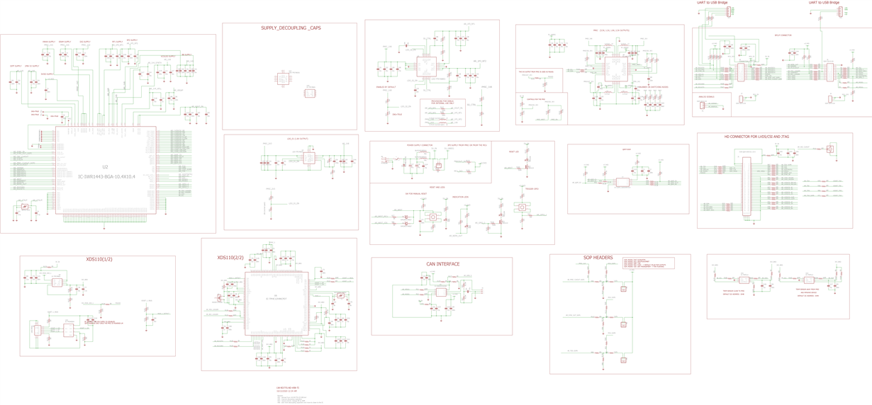
    The schematic as an image file is attached for your preview. The new schematic with the PMIC being replaced by linear LDO's is being prepared and will be sent out once available. The chip should be in the functional mode as it can provide acknowledgment message of 'Done' after CLI commands are sent to the chip (please see the Python output log file as attached). I will check the voltages after power up to make sure they are all ok.

    5811.iwr1443 board Python output log.txt
    C:\Users\admin\AppData\Local\Programs\Python\Python35\python.exe "F:/software/Python/Lexiwave 77G using AWR1642 v128i5b4_ad.py"
    sensorStop
    
    Done
    
    mmwDemo:/>flushCfg
    
    Done
    
    mmwDemo:/>dfeDataOutputMode 1
    
    Done
    
    mmwDemo:/>channelCfg 15 5 0
    
    Done
    
    mmwDemo:/>adcCfg 2 1
    
    Done
    
    mmwDemo:/>adcbufCfg 0 1 0 1
    
    Done
    
    mmwDemo:/>profileCfg 0 77 429 7 57.14 0 0 70 1 240 4884 0 0 30
    
    Done
    
    mmwDemo:/>chirpCfg 0 0 0 0 0 0 0 1
    
    Done
    
    mmwDemo:/>chirpCfg 1 1 0 0 0 0 0 4
    
    Done
    
    mmwDemo:/>frameCfg 0 1 16 0 500 1 0
    
    Done
    
    mmwDemo:/>lowPower 0 1
    
    Done
    
    mmwDemo:/>guiMonitor 0 0 0 1 0 0
    
    Done
    
    mmwDemo:/>cfarCfg 0 2 8 4 3 0 1280
    
    Done
    
    mmwDemo:/>peakGrouping 1 1 1 1 229
    
    Done
    
    mmwDemo:/>multiObjBeamForming 1 0.5
    
    Done
    
    mmwDemo:/>clutterRemoval 0
    
    Done
    
    mmwDemo:/>calibDcRangeSig 0 -5 8 256
    
    Done
    
    mmwDemo:/>compRangeBiasAndRxChanPhase 0.0 1 0 1 0 1 0 1 0 1 0 1 0 1 0 1 0 1 0 1 0 1 0 1 0
    
    Done
    
    mmwDemo:/>measureRangeBiasAndRxChanPhase 0 1.5 0.2
    
    Done
    
    mmwDemo:/>CQRxSatMonitor 0 3 5 123 0
    
    Done
    
    mmwDemo:/>CQRxSatMonitor 0 3 5 123 0
    
    Done
    
    mmwDemo:/>CQSigImgMonitor 0 119 4
    
    Done
    
    mmwDemo:/>analogMonitor 1 1
    
    Done


  • Hello,

        Thank you for sharing the schematic, could you please post the pdf file? It's difficult to review with image file. 

    Thanks and regards,

    CHETHAN KUMAR Y.B.

  • Here you go. Do you know the function of pin WARM_RESET? I know it can be either input or output. Also, for NERROR_IN, is it active low meaning fault input from an external device?

    HenryLW-RD77G-AD-V08-TI.pdf

  • Hello Henry,

          Thank you, We may need a week to review the schematic and provide you the feedback.

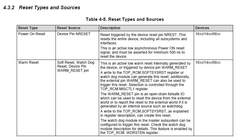
    For the Warm reset you could refer to Technical reference manual for more details.

    I have added description table from TRM for your reference.

    For NERROR_IN your understanding is correct, It is also active low signal to propagate any fault occurring from the other safety sub-system such as PMIC or processor which would be propagated indicating a fault in the system. 

    Thanks and regards,

    CHETHAN KUMAR Y.B. 

  • Hello Henry,

      Reposting the image as table did not come correct in the above post...

    Thanks and regards,

    CHETHAN KUMAR Y.B.

  • Hi Chethan,

    Really appreciate for the information. Looking forward to receiving your feedback on the schematic review. The sooner the better.

    Another question: there is no output from MCU_CLKOUT pin. Is it supposed to have no output for SDK_2.1.04?

    Thanks a lot,

    Henry

  • Hi Chethan,

    The chip sends acknowledgement for receiving the 'SensorStart' command to the com port. The WARM_RESET pin goes LOW for a short duration and goes back to HIGH. Is that normal?

    Thanks a lot,

    Henry 

  • Hendry,

       Warm_reset going low for short duration is normal, you could refer to previous Wakeup diagram it is shown and expected behavior. 

    Thanks and regards,

    CHETHAN KUMAR Y.B.

  • Hi Chethan,

    The updated schematic is attached for your review. The onboard XS110 chip is not on the board for the moment. The UART ports of the radar chip  are now connected to the XDS110 chip of a CC1310 Launchpad. The CC1310 Launchpad is then connected to a PC. I used Visualizer to test iwr1443boost evm and the custom board. The log files are attached.

    'visualizer2103 lw board message.txt' - from custom board

    visualizer2103 iwr1443boost.txt - from iwr1443boost evm.

    Result plot came out from the iwr1443boost evm but not from the custom board. The 'done' message can be received after 'sensorStart' command on iwe1443boost but this was received on the custom board:

    " ÿ******************************************

    xWR14xx MMW Demo 02.01.00.04

    ****************************************** "

    Not sure this will give some clues on the issue.

    Thanks a lot,

    Henry

    visualizer2103 lw board message.txt
    mmwDemo:/>% ***************************************************************
    Skipped
    
    mmwDemo:/>% Created for SDK ver:02.01
    Skipped
    
    mmwDemo:/>% Created using Visualizer ver:2.1.0.3
    Skipped
    
    mmwDemo:/>% Frequency:77
    Skipped
    
    mmwDemo:/>% Platform:xWR14xx
    Skipped
    
    mmwDemo:/>% Scene Classifier:best_range_res
    Skipped
    
    mmwDemo:/>% Azimuth Resolution(deg):15
    Skipped
    
    mmwDemo:/>% Range Resolution(m):0.044
    Skipped
    
    mmwDemo:/>% Maximum unambiguous Range(m):9.01
    Skipped
    
    mmwDemo:/>% Maximum Radial Velocity(m/s):1
    Skipped
    
    mmwDemo:/>% Radial velocity resolution(m/s):0.13
    Skipped
    
    mmwDemo:/>% Frame Duration(msec):1000
    Skipped
    
    mmwDemo:/>% Range Detection Threshold (dB):15
    Skipped
    
    mmwDemo:/>% Range Peak Grouping:enabled
    Skipped
    
    mmwDemo:/>% Doppler Peak Grouping:enabled
    Skipped
    
    mmwDemo:/>% Static clutter removal:disabled
    Skipped
    
    mmwDemo:/>% ***************************************************************
    Skipped
    
    mmwDemo:/>sensorStop
    Done
    
    mmwDemo:/>flushCfg
    Done
    
    mmwDemo:/>dfeDataOutputMode 1
    Done
    
    mmwDemo:/>channelCfg 15 5 0
    Done
    
    mmwDemo:/>adcCfg 2 1
    Done
    
    mmwDemo:/>adcbufCfg 0 1 0 1
    Done
    
    mmwDemo:/>profileCfg 0 77 429 7 57.14 0 0 70 1 240 4884 0 0 30
    Done
    
    mmwDemo:/>chirpCfg 0 0 0 0 0 0 0 1
    Done
    
    mmwDemo:/>chirpCfg 1 1 0 0 0 0 0 4
    Done
    
    mmwDemo:/>frameCfg 0 1 16 0 1000 1 0
    Done
    
    mmwDemo:/>lowPower 0 1
    Done
    
    mmwDemo:/>guiMonitor 1 0 0 0 0 0
    Done
    
    mmwDemo:/>cfarCfg 0 2 8 4 3 0 1280
    Done
    
    mmwDemo:/>peakGrouping 1 1 1 1 229
    Done
    
    mmwDemo:/>multiObjBeamForming 1 0.5
    Done
    
    mmwDemo:/>clutterRemoval 0
    Done
    
    mmwDemo:/>calibDcRangeSig 0 -5 8 256
    Done
    
    mmwDemo:/>compRangeBiasAndRxChanPhase 0.0 1 0 1 0 1 0 1 0 1 0 1 0 1 0 1 0 1 0 1 0 1 0 1 0
    Done
    
    mmwDemo:/>measureRangeBiasAndRxChanPhase 0 1.5 0.2
    Done
    
    mmwDemo:/>CQRxSatMonitor 0 3 5 123 0
    Done
    
    mmwDemo:/>CQSigImgMonitor 0 119 4
    Done
    
    mmwDemo:/>analogMonitor 1 1
    Done
    
    mmwDemo:/>sensorStart
    ÿ******************************************
    
    xWR14xx MMW Demo 02.01.00.04
    
    ******************************************
    visualizer2103 iwr1443boost.txt
    mmwDemo:/>% ***************************************************************
    Skipped
    
    mmwDemo:/>% Created for SDK ver:02.01
    Skipped
    
    mmwDemo:/>% Created using Visualizer ver:2.1.0.3
    Skipped
    
    mmwDemo:/>% Frequency:77
    Skipped
    
    mmwDemo:/>% Platform:xWR14xx
    Skipped
    
    mmwDemo:/>% Scene Classifier:best_range_res
    Skipped
    
    mmwDemo:/>% Azimuth Resolution(deg):15
    Skipped
    
    mmwDemo:/>% Range Resolution(m):0.044
    Skipped
    
    mmwDemo:/>% Maximum unambiguous Range(m):9.01
    Skipped
    
    mmwDemo:/>% Maximum Radial Velocity(m/s):1
    Skipped
    
    mmwDemo:/>% Radial velocity resolution(m/s):0.13
    Skipped
    
    mmwDemo:/>% Frame Duration(msec):1000
    Skipped
    
    mmwDemo:/>% Range Detection Threshold (dB):15
    Skipped
    
    mmwDemo:/>% Range Peak Grouping:enabled
    Skipped
    
    mmwDemo:/>% Doppler Peak Grouping:enabled
    Skipped
    
    mmwDemo:/>% Static clutter removal:disabled
    Skipped
    
    mmwDemo:/>% ***************************************************************
    Skipped
    
    mmwDemo:/>sensorStop
    Done
    
    mmwDemo:/>flushCfg
    Done
    
    mmwDemo:/>dfeDataOutputMode 1
    Done
    
    mmwDemo:/>channelCfg 15 5 0
    Done
    
    mmwDemo:/>adcCfg 2 1
    Done
    
    mmwDemo:/>adcbufCfg 0 1 0 1
    Done
    
    mmwDemo:/>profileCfg 0 77 429 7 57.14 0 0 70 1 240 4884 0 0 30
    Done
    
    mmwDemo:/>chirpCfg 0 0 0 0 0 0 0 1
    Done
    
    mmwDemo:/>chirpCfg 1 1 0 0 0 0 0 4
    Done
    
    mmwDemo:/>frameCfg 0 1 16 0 1000 1 0
    Done
    
    mmwDemo:/>lowPower 0 1
    Done
    
    mmwDemo:/>guiMonitor 1 0 0 0 0 0
    Done
    
    mmwDemo:/>cfarCfg 0 2 8 4 3 0 1280
    Done
    
    mmwDemo:/>peakGrouping 1 1 1 1 229
    Done
    
    mmwDemo:/>multiObjBeamForming 1 0.5
    Done
    
    mmwDemo:/>clutterRemoval 0
    Done
    
    mmwDemo:/>calibDcRangeSig 0 -5 8 256
    Done
    
    mmwDemo:/>compRangeBiasAndRxChanPhase 0.0 1 0 1 0 1 0 1 0 1 0 1 0 1 0 1 0 1 0 1 0 1 0 1 0
    Done
    
    mmwDemo:/>measureRangeBiasAndRxChanPhase 0 1.5 0.2
    Done
    
    mmwDemo:/>CQRxSatMonitor 0 3 5 123 0
    Done
    
    mmwDemo:/>CQSigImgMonitor 0 119 4
    Done
    
    mmwDemo:/>analogMonitor 1 1
    Done
    
    mmwDemo:/>sensorStart
    Done

    LW-RD77G-AD-V11-TI.pdf

  • Hello Henry,

        Please review below cautionary note when XDS110 or UART drivers not on the same VIO of the mmWave sensor,

    There could be incorrect boot mode setting making device not to output anything.

    https://e2e.ti.com/support/sensors/f/1023/t/948210

    Thanks and regards,

    CHETHAN KUMAR Y.B.

  • Hi Chethan,

    Thanks for the hint. I will check it out.

    Another question I have:

     Do the supply pin VIN_13RF1 and VIN_13RF2 require 1.0V or 1.3V with SDK_2.1.04. The iwr1443boost board seems using 1.0V (assuming it uses internal LDO) but my custom board is using 1.3V. Will it be the cause of the problem I am having? Will 1.3V damage the part if the LDO is bypassed?

    Henry

  • Henry,

        Yes this will be problem, 1.3V directly cannot be applied to RF circuits, If the internal LDO is bypassed then it would directly applied to LNA and PA. This will be reliability problem for the RF circuits.

    Thanks and regards,

    CHETHAN KUMAR Y.B

  • Hi Chethan,

    Finally, I got it up and running. Seems the LDO on the custom board for  VIN_13RF1 and VIN_13RF2 is having problem. I used a power supply of 1.25V for it and the chip is now working. Need to figure out if it is the driving capability or the power-up settling time of the LDO is causing problem. Will keep you posted shortly.

    Really appreciated for you help.

    Henry

  • Henry,

        Wow, Thank you for the confirmation, all the best for the, next stage of your activities.  

    Thanks and regards,

    CHETHAN KUMAR Y.B.

  • Hi Chethan,

    Do you how which register to bypass the internal LDO for VIN_13RF1 and VIN_13RF2? Not sure if it is bypassed with SDK_2.1.04?

    Also, does TI have demo code for 3TX and 4RX to form virtual antenna of 12?

    Thanks again,

    Henry