This thread has been locked.

If you have a related question, please click the "Ask a related question" button in the top right corner. The newly created question will be automatically linked to this question.

PGA460PSM-EVM: Sensor not working: All 550001FE burst & listen preset1 command result in same 5505FA result of 4082 5627 8433

Part Number: PGA460PSM-EVM
Other Parts Discussed in Thread: BOOSTXL-PGA460, PGA460, MSP-EXP430F5529LP, PGA460-Q1, MSP430F5529,

I have my own UART interface and it seems the default EEPROM values might not be correct for the sensor supplied?  The BoM states the sensor is:

U2 1 Ultrasonic Xmr/Receiver, TH Dia 14.4mm UTR-1440K-TT-R PUI Audio

which is a 40kHz device, the default EEPROM value for freq is C8=> 60kHz

Command 550BF4 EEPROM Dump results in:

4000 0000 0000 0000 0000 0000 0000 0000 0000 0000
00AF FFFF 2D68 36FC C08C 0001 1247 FF1C 00EE 7C0A 0000 0000 0E00

Command 5508F7 diagnostic results in: 4088 1324 00 at both 9600 & 115200 baud

Command 550001FE burst & listen preset1, never drives the SONAR sensor  (12V, 800mA capable power supply)

Can I get the correct EEPROM data for this device or is there another problem I'm not seeing?  I don't want to buy more dongles for debugging if I don't have to.

  • Hi Robert,

    Table 6 of the PGA460 datasheet shows the EEPROM Factory Default Values. For frequency, the default EEPROM value is 0x8C, which corresponds to a default frequency of 58 kHz. The BOOSTXL-PGA460 board uses a 58 kHz transducer so the transducer frequency setting would not have to be changed when using this board. On the other hand, the PSM board that you are using has a 40 KHz frequency, so the EEPROM frequency value would have to be modified to correspond to this 40 kHz frequency.

    In addition to setting the proper transducer frequency, please also make sure to write to the corresponding threshold registers if you haven’t done this already. Please note that the threshold registers are not in EEPROM, so you will have to initialize these registers after each time the PGA460 is reset or wakes up from low power mode.

    Regards,

    Mekre

  • To further assist with this problem, I purchased a msp-exp430f5529lp eval board to use the PGA460-Q1 EVM.  The PGA460-Q1 EVM now detects a USB as shown in attached screen shot.  But there is no output on the UART pins from the msp-exp430f5529lp eval board when I press [Check of PGA460-Q1] on any TX/RX pins on either side the the eZ-FET lite header.  I sure hope I don't need to buy another module (BoosterPack?) just to test the PGA460 eval board out.  I expected it to run straight out of the box, not require a string of tools just to configure the already attached SONAR xDucer.

  • Hi Robert,

    The links seem to be broken. Could you try to upload the attachments again?

    Also, the following video may help you set the BOOSTXL-PGA460 kit:

    https://training.ti.com/pga460-ultrasonic-sensing-how-set-and-install-evm?context=1128182-1128152

    Regards,

    Mekre

  • Thanks kindly for the reply.  However, my main question is two parts:

    1) I do not want to buy another module,  BOOSTXL-PGA46 is too expensive just to configure the PGA460 I already bought followed by the msp-exp430f5529lp. Can I use just the eval boards I already have to configure an test the PGA-460?

    2) My msp-exp430f5529lp has no UART output activity.  I have loaded the 460 bootloader onto this eval board.  What could be causing this?

    I no longer have the images I attached.  Please answer specifically 1) & 2)

  • Hi Robert,

    If you are not using the TCI or OWU interfaces, you should be able to use the MSP430F5529 LaunchPad with the PGA460PSM-EVM without the BoosterPack. To evaluate the PGA460-Q1 in USART mode, connect the following to the J2 connector of the PGA460PSM-EVM:

    • J2-1: PWR to the positive terminal of a power supply at 6 V to 28 V
    • J2-2: GND to the negative terminal of a power supply
    • J2-3: TXD to the master controller's UART RXD pin (MSP-EXP430F5529LP P3.4) or SPI MISO pin (MSP-EXP430F5529LP P3.1)
    • J2-4: RXD to the master controller's UART TXD pin (MSP-EXP430F5529LP P3.3) or SPI MOSI pin (MSP-EXP430F5529LP P3.0)
    • J2-5: SCLK to the master controller's SPI CLK pin (MSP-EXP430F5529LP P3.2)

    To test your UART connection, you could probe pins P3.3 and P3.4 to see if there is any activity on these pins when you do a burst and listen command. You can initiate a burst and listen command by first clicking on the “Data Monitor” field at the top left of the GUI window and then clicking on the “START” button at the bottom middle of the GUI screen. You may want to perform this test both when a PGA460 is connected and also when a board is not connected.

    Regards,

    Mekre

  • Mekre,

    Your last reply was very helpful in getting the GUI to work.  I was mislead by the MSP430F5529 LaunchPad's pins labeled TX & RX, they were not the correct UART pins.

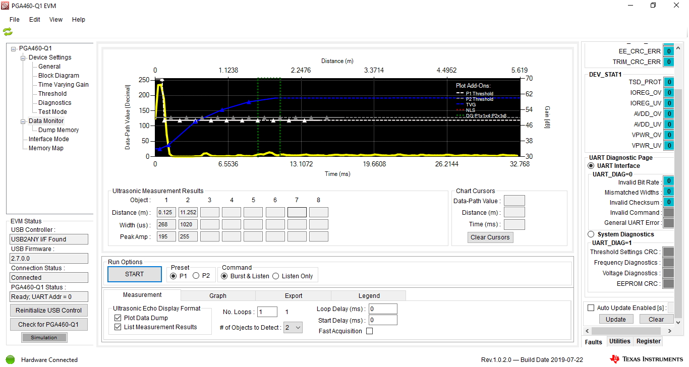
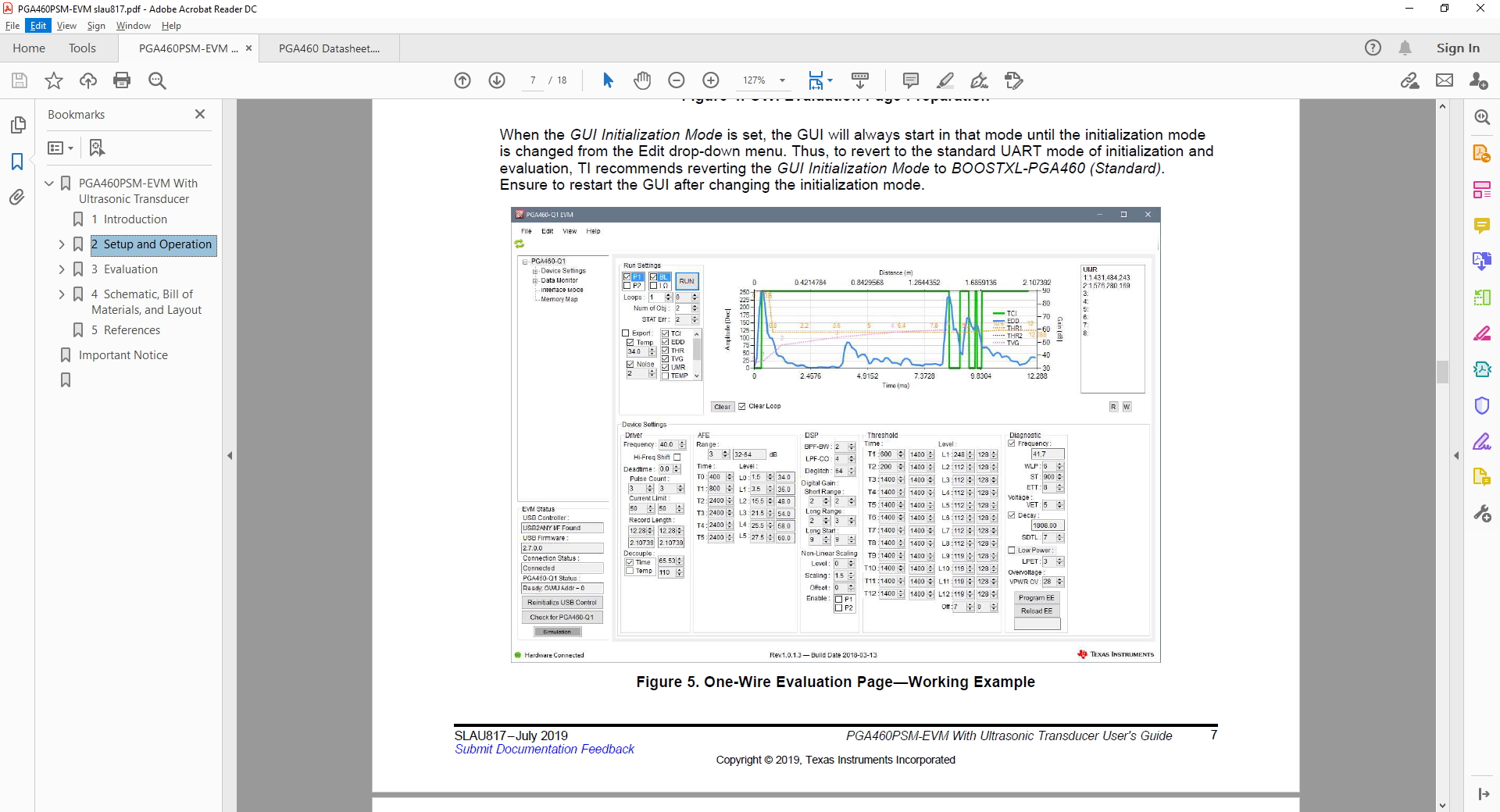
    Now my problem is getting the PGA460-Q1 configured and optimized.  The second image below is the GUI configuration from the slau817.pdf.  The result after I configured the GUI and ran the test is shown below. My tage was at about 1.5m.  Since I recently bought the PGA460-Q1, I thought there should be an existing up-to-date configuration example.  Can you please run a test with the same parts I have and/or provide me with proper setup values so I can continue to evaluate and deploy this module?  I have customers ready to buy in the transportation industry if I can get this to work in a timely fashion.

    thanks in advance,

    Robert

  • Hi Robert,

    In one of our code examples that used the same transducer used in the PGA460PSM-EVM, the following default values were used:

                                     TVGAIN0 = 0x9D;

                                     TVGAIN1 = 0xEE;

                                     TVGAIN2 = 0xEF;

                                     TVGAIN3 = 0x2D;

                                     TVGAIN4 = 0xB9;

                                     TVGAIN5 = 0xEF;

                                     TVGAIN6 = 0xDC;

                                     INIT_GAIN = 0x03;

                                     FREQUENCY = 0x32;

                                     DEADTIME = 0x80;

                                     PULSE_P1 = 0x08;

                                     PULSE_P2 = 0x12;

                                     CURR_LIM_P1 = 0x72;

                                     CURR_LIM_P2 = 0x32;

                                     REC_LENGTH = 0x09;

                                     FREQ_DIAG = 0x33;

                                     SAT_FDIAG_TH = 0xEE;

                                     FVOLT_DEC = 0x7C;

                                     DECPL_TEMP = 0x8F;

                                     DSP_SCALE = 0x00;

                                     TEMP_TRIM = 0x00;

                                     P1_GAIN_CTRL = 0x09;

                                     P2_GAIN_CTRL = 0x29;

    You can use these values as a starting point and then change values as necessary to optimize for your specific system and target. The following video series provides examples on configuring the GUI:

    https://training.ti.com/pga460-ultrasonic-sensing-how-set-and-install-evm?context=1128182-1128152

    Regards,

    Mekre