This thread has been locked.

If you have a related question, please click the "Ask a related question" button in the top right corner. The newly created question will be automatically linked to this question.

PGA460: MSB/LSB selection for transmitted data samples in Direct-Data-Burst 8-bit mode with SAMPLE_SEL=0

Part Number: PGA460

To analyze data with synchronous direct data burst, I used 12bit sampled data until now with SAMPLE_SEL=1. This works fine. But now I would like to test 8bit data with SAMPLE_SEL=0.
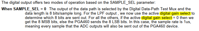
The descrition in the datasheet is not clear to me. Following you can see the datasheet description:

This are my questions:
1) What is meant by 'digital gain select'. There is no further explanation in the datasheet.
2) What is the difference betwenn LPF-Output and 'all others'.
3) The DP_MUX selects datapath, SAMPLE_SEL selects data width, but what selects LSB/MSB.

The only thing I could find with similar naming, are registers P1_GAIN_CTRL and P2_GAIN_CTRL for digital gain configuration.
These registers hold some settings which are named with DIG_GAIN_LR_ST, DIG_GAIN_LR, DIG_GAIN_SR.
But there is no similarity to  'digital gain select'.

  • Hi Mathias,

    Section 7.3.4.5 of the datasheet has more info on the digital gain.

    The PGA460 has the option to output data from different stages within its AFE block. The different options are shown as the inputs to the Test Mux block shown in Figure 35 and include the LPF output, rectifier output, BPF output, or ADC output.  The output is selected with the DP_MUX bits in the TEST_MUX register.

    For the LPF  output option, you can specifically select which 8 bits to send out.  The digital gain options are in powers of 2.  Each multiply by 2 corresponds to shifting the data to the left by 1, so you can choose which bits to output by choosing the appropriate digital gain multiplier option.

    For the rectifier output, BPF output, and ADC output, you can only select whether you want to output the 8 MSB bits or the 8 LSB bits.  For these three options, you do not have the capability to choose anything besides the 8 MSB and 8 LSB bits.

    Regards,

    Mekre    

  • Hi Mekre,

    for LPF which gain setting has to be used, DIG_GAIN_LR or DIG_GAIN_SR ?

    for rectifier output, BPF output and ADC output only 8bit MSB or 8bit LSB can be selected. Which setting has to be used to select MSB or LSB.

    Regards,

    Mathias 

  • Hi Mathias,

    For the rectifier output, BPF output, and ADC output, you can select the 8 MSB bits by setting the digital gain select value=0 (this corresponds to a digital gain of 1).  All other values of the digital gain select value would result in the 8 LSB bits being sent.

    Regards,

    Mekre

  • Hi Mekre,

    I'm sorry, but your answer ist not clear. The term 'digital gain select' is not specified in the datasheet.

    Please tell me exactly which of the various gain settings is responsible for 8bit sample selection for LPF-Output and the other others (rectifier,BPF,ADC).

    Below you can see the GAIN_CTRL Register. Is it short range gain select  (DIG_GAIN_SR) or long range gain select (DIG_GAIN_LR) , or something else ?

    Regards

    Mathias

  • Hi Mathias,

    I would first recommend trying to set both P1_DIG_GAIN_LR and P1_DIG_GAIN_SR to a value of 0 (multiplied by 1) for getting the MSB. To get the LSB instead, you can try a nonzero value for the P1_DIG_GAIN_LR and P1_DIG_GAIN_SR fields.

    Regards,

    Mekre