This thread has been locked.

If you have a related question, please click the "Ask a related question" button in the top right corner. The newly created question will be automatically linked to this question.

TDC7200: Delay factor for Time-of-Flight

Part Number: TDC7200

HI,

TDC7200 explains Calculating Time of flight in chapter 8.4.2.1.1. and would like to know all of delay factor from ToF time such as SPI communication time.

1) How will it take time to set MEAS_COMPLETE_FLAG in INT_STATUS after receiving STOP?

2) The chapter  8.4.2.1.1. in datasheet explain how to calculate the ToF time and EVM can calculate the time. Will it include SPI time?
e.g. If the ToF time from start to stop is 19us. May system have 19us + SPI time(=50ns * 16 pulse)?

Regards,
Nagata.

  • Hi Nagata,

    1)  It takes between 1-2 micro-seconds after the last STOP for the INTB interrupt to generate. This is the first available indicator that the measurement is complete, and should be used to determine measurement completion. An experiment using the host MCU could be run to approximate the latency between INTB and the register population. 

    2) The ToF calculation example in the datasheet does not include any overhead time for setting INTB, calibration, or SPI communication. Please see datasheet section 8.4.2 for more details. 

    Regards,

    Gabriel

  • Gabriel,

    Could you please break down about your comment for 2)? User would like to know total ToF time include SPI and calibration.

    - When will calibration run? Will it include from Start to Stop?

    - How long will it take time for each calibration?

    - Could you please let me know the total time for host to receive the packet.
    I guess it may TOFx time + SPI time(=50ns * 16 pulse) . Is it correct? Or will it TOFx time + SPI time(=50ns * 16 pulse) + calibration(?? sec)?

    Regards,
    Nagata.

  • Nagata,

    - There are two calibrations, one occurs just before the trigger pulse is sent (between START_MEAS and TRIGG). The second calibration occurs at the very end of the measurement, before INTB is driven low. 

    - The time taken for calibration varies depending on the external clock frequency and the number of clock periods specified for calibration. Calibration 1 is always over one clock period, and calibration 2 can be done over 2, 10, 20, or 40 clock periods. Measure the time between START_MEAS and TRIGG to estimate the calibration time. For calibration 2, what we know from other customers is that it completes and INTB goes low in under 2 micro-seconds typically. 

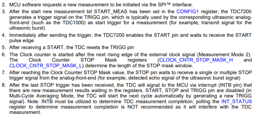
    - The time breakdown for a measurement can be taken from the measurement sequence description in the datasheet, steps 2 - 8: 

    There will be a latency between setting the START_MEAS bit and when the START pulse is seen by the TDC7200 (Tpre-meas), and there is also latency time between STOP and INTB (Tpos-meas). The time between START and STOP would just be the ToF. 

    Tpre-meas = Tspi + T2trigg + Ten + T2start

    Tpos-meas = Tcal2 + T2intB

    Tspi = SPI communication time, which can be estimated as you have shown or by measuring the time CSB is low. 

    T2trigg = time between START_MEAS is set and the TRIGG pulse is asserted, including the time taken to complete calibration 1

    Ten = time for the TDC7200 to enable the START input pin. 

    T2start = time between TRIGG received by the AFE and the START is received by the TDC7200

    Tcal2 = time for calibration 2 to complete

    T2intB = time between cal2 completion and INTB going low, overhead time for measurement registers and status registers to be set, etc. 

    As soon as INTB is low, the host controller is able to retrieve the data via SPI. The overall time depends on user selections, the host controller, and clock speeds. I recommend that customers take measurements with their own system when accurate timing information is needed, but if this option is not available, this information can be used to estimate measurement latencies. 

    Regards,

    Gabriel