This thread has been locked.

If you have a related question, please click the "Ask a related question" button in the top right corner. The newly created question will be automatically linked to this question.

TDC7200: TDC7200 INTB question

Part Number: TDC7200

Hi,

We had TDC7200 INTB questions to you?

We use 1.2K or 100K Hz LD trigger (STOP) to occue INTBs.
But TDC7200 got interupt INTB about 600 per second (0.6 KHz).
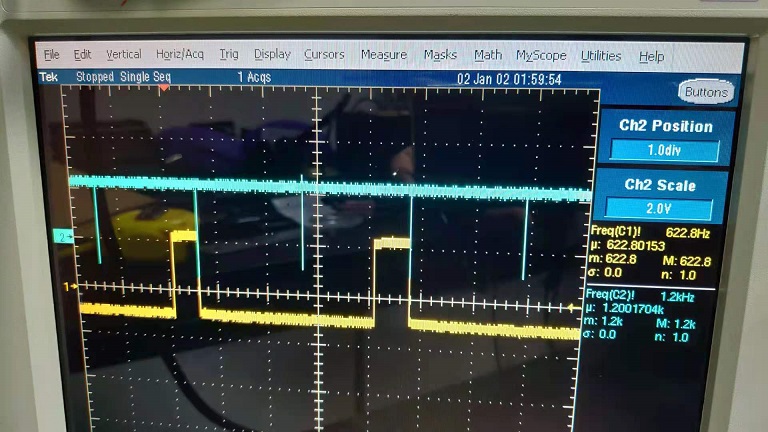
(Refer to P1_TDC7200.jpg, Yellow line is INTB and Blue line is STOP)

(1) Why we got one INTB every 2 Measurement Cycle when Measurement Cycle is set to 1 ? (Refer to P1_TDC7200.jpg)
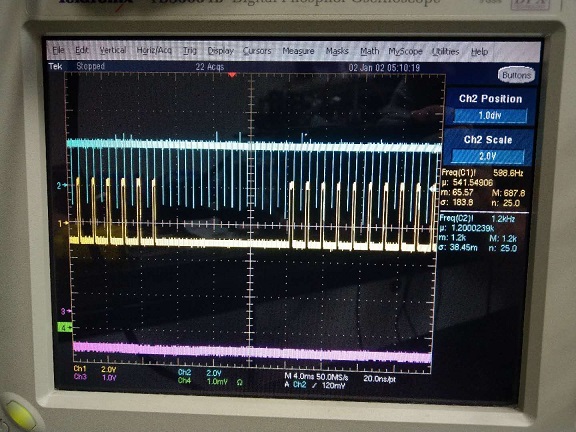
(2) Why we sometime got no INTB response after 17 STOP ? (Refer to P2_TDC7200.jpg)
(3) How to increase INTB to 100K ?

-----------------------------------------------------------------------------------------------------
Our FW settings as follows,
  TI_TDC720x_SPIByteWriteReg(TI_TDC720x_CONFIG1_REG, 0x11, dev); // Default Mode 2
  TI_TDC720x_SPIByteWriteReg(TI_TDC720x_CONFIG2_REG, 0x40, dev); // cal2 period = 10 clocks
  TI_TDC720x_SPIByteWriteReg(TI_TDC720x_INTRPT_STATUS_REG, 0x0B, dev); // clear interrupt status
  TI_TDC720x_SPIByteWriteReg(TI_TDC720x_INTRPT_MASK_REG, 0x07, dev); // interrupts enabled
  TI_TDC720x_SPIByteWriteReg(TI_TDC720x_COARSE_COUNTER_OVH_REG, 0xFF, dev); // default
  TI_TDC720x_SPIByteWriteReg(TI_TDC720x_COARSE_COUNTER_OVL_REG, 0xFF, dev); // default
  TI_TDC720x_SPIByteWriteReg(TI_TDC720x_CLOCK_COUNTER_OVH_REG, 0xFF, dev); // default
  TI_TDC720x_SPIByteWriteReg(TI_TDC720x_CLOCK_COUNTER_OVL_REG, 0xFF, dev); // default
  TI_TDC720x_SPIByteWriteReg(TI_TDC720x_CLOCK_COUNTER_STOP_MASKH_REG, 0x00, dev); // default
  TI_TDC720x_SPIByteWriteReg(TI_TDC720x_CLOCK_COUNTER_STOP_MASKL_REG, 0x00, dev); // default

P1_TDC7200.jpg :

P2_TDC7200.jpg :

  • Hello,

    Can you provide some more details about the application?

    - At what frequency are measurements initiated?

    - What is the external clock frequency?

    - What is the supply voltage VDD?

    Also Note:

    Regards,

    Gabriel

  • Hi Gabriel,


    Can you provide some more details about the application?
       Reply: We apply to Lidar detect about the distance range of 0.05M ~ 25M. (Refer TI of TIDA00663 solution)

    - At what frequency are measurements initiated?
      Reply: Picture is 1.2KHz sample rate. Target is 100KHz sample rate.

    - What is the external clock frequency?
      Reply: TDC clock frequency is 16Mhz

    - What is the supply voltage VDD?
      Reply: MCU VDD is 3.3V.

    About Note:

    TI_TDC720x_SPIByteWriteReg(TI_TDC720x_CONFIG1_REG, 0x11, dev); // Measurement Mode 1 and STOP EDGE is falling edge
                                        => Correct our wrong note describtion that we use mode 1 and failing edge by receive laser side HW(ox11).
                                           And our emit laser side is set to 0x01 for  STOP EDGE is rising edge.
                                           Our application is short distance range so choose the Measurement Mode 1.


    Best Regards,
    Alvin

  • Alvin, 

    Thanks for the clarification. In the first scope plot INTB is staying low through next STOP, are you sure that a new measurement is being initiated on time? INTB should reset along with the measurement result registers when the START_MEAS bit is set to start a new measurement. SPI communication with the device should happen after INTB low is detected. Also, after the STOP is received, INTB can take up to 2us to assert low. 

    Regards,

    Gabriel